
Method for controlling gear shifting of a working machine

a gear shifting and working machine technology, applied in the direction of steering parts, external condition input parameters, constructions, etc., can solve the problems of reducing the traction force of the working machine, and affecting the driving experience of the driver, so as to reduce the vehicle speed and the available total traction force, the effect of speeding up and lowering the drop in vehicle speed

Active Publication Date: 2019-09-17
VOLVO CONSTR EQUIP AB
View PDF18 Cites 0 Cited by
  • Summary
  • Abstract
  • Description
  • Claims
  • Application Information

AI Technical Summary

Benefits of technology

This approach allows for smooth gear shifting without substantial speed drops, maintaining vehicle traction and efficiency, even on steep slopes, by compensating torque and tractive force across drive units.

Problems solved by technology

If the torque applied to one of the drive units is significantly reduced to allow shifting of gear for that particular drive unit, the tractive force of the working machine is correspondingly reduced which in turn results in a drop in speed or acceleration.
This is not only unpleasant for the driver but can have various negative effects, such as inducing safety risks, taking time / reducing efficiency and making it more problematic to advance upwards a steep slope.
In the inventive method the torque and tractive force of the drive unit(s) subject to gear shifting is not allowed to be reduced to the low level suitable for shifting gear, which in turn means that gear shifting is not allowed, if the available total traction force is not sufficient.
But whether the increased load / torque of the other drive units really results in a correspondingly increased traction force is not addressed.

Method used


Image

  • Method for controlling gear shifting of a working machine
  • Method for controlling gear shifting of a working machine
  • Method for controlling gear shifting of a working machine

Examples


Embodiment Construction

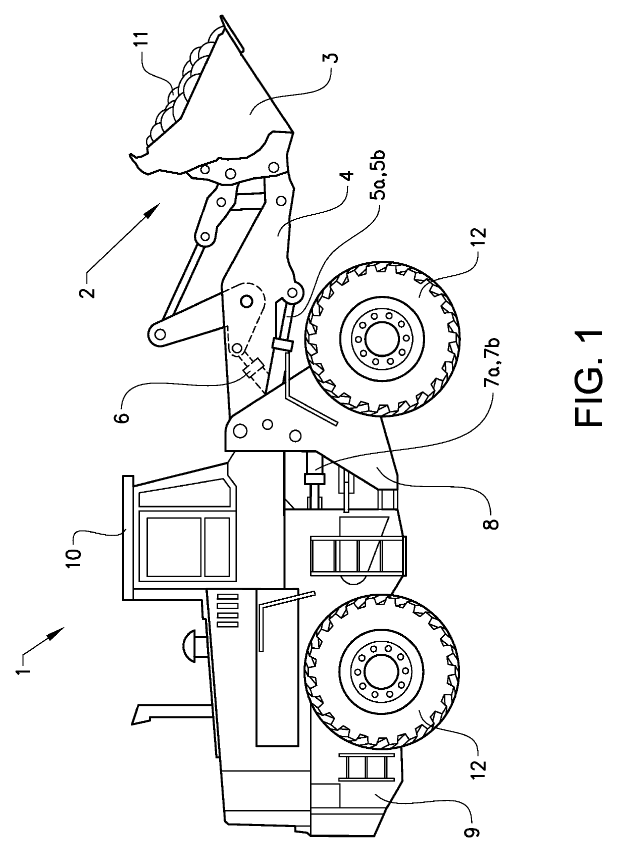
[0072]FIG. 1 shows a working machine 1 in the form of a wheel loader. The wheel loader 1 is to be considered as an example of a working machine having a drive system to which the method according to the invention can be applied.

[0073]The wheel loader 1 has a forward machine part / front frame 8 and a rear machine part / rear frame 9. Each of the machine parts / frames comprises two drive wheels 12. The rear machine part 9 comprises a cab 10 for an operator of the wheel loader 1. The machine parts 8, 9 are connected to each other in such a way that they can pivot relative to each other about a vertical axis by means of two hydraulic cylinders (steering cylinders) 7a, 7b which are arranged between the machine parts 8, 9 and attached thereto. The hydraulic cylinders 7a, 7b are thus arranged one on each side of a centre line extending in the longitudinal direction of the working machine 1 in order to turn or steer the wheel loader by means of the hydraulic cylinders. In other words, the wheel...


PUM


Abstract

A method for controlling gear shifting of a working machine includes determining a representation of a first total tractive force of the working machine for the entire set of drive units; initiating a procedure for redistributing the tractive force while maintaining the first total tractive force, including decreasing, at least partly towards a level suitable for shifting gear, the torque and tractive force of at least the first drive unit down, and increasing, in a compensational manner, the torque and tractive force of at least one of the other drive units not subject to gear shifting; monitoring, during the redistribution procedure, a representation of a second total tractive force of the working machine for the other drive units not subject to gear shifting, and, provided that the second total tractive force exceeds a threshold limit that forms a function of the first total tractive force: decreasing the torque and tractive force of at least the first drive unit down to the level suitable for shifting gear and performing gear shifting for at least the first drive unit.

Description

BACKGROUND AND SUMMARY[0001]This invention relates to a method for controlling gear shifting of a working machine provided with a set of independent drive units, such as an articulated, frame steered vehicle having four single-wheel electric hub motors.[0002]A working machine, such as a front loader, wheel loader or an articulated hauler, is provided with a bucket, container or other type of implement for lifting, carrying and / or transporting a load. The drive system of such a working machine conventionally includes a single drive motor, such as a diesel engine, that drives all drive wheels via a single gearbox for matching the drive power to different driving conditions. The driveline may include a torque converter.[0003]More recent working machines may include several independent drive units including, for instance, four drive wheels that are driven either axle-wise by two separate drive units, i.e. a front axle drives two front wheels and a rear axle drives two rear wheels, or vi...

Claims


Application Information

Patent Timeline
Patent Type & Authority Patents(United States)
IPC IPC(8): B60W30/18E02F9/20B60W30/19B60W10/10B60K7/00B60K23/08B60W10/08B60W10/04E02F9/22B62D12/00
CPCB60W10/10B60W30/18172B60K7/0007B60W30/19B60K23/0808B60W10/08E02F9/2079B60W10/04E02F9/207B60W2300/17B60K2007/0038B60W2520/10B60W2710/1005B60W2520/30B60Y2200/415B60W2520/26B60W2520/403B62D12/00B60K2007/0092E02F9/2253B60W2720/406B60W2510/083B60W2720/26B60W2520/406B60W2720/30B60W2720/403B60Y2200/412B60W2710/083B60W2552/40
Inventor ANDERSSON, THOMASÅKERBLOM, MATS
Owner VOLVO CONSTR EQUIP AB
Learn More