Modular assembly for handling excavating equipment for excavating machines, excavating machine, method for converting the excavating configuration of an excavating machine

a technology of modular assembly and excavating equipment, which is applied in the direction of drilling with mechanical conveying, drilling accessories, drilling machines and methods, etc., can solve the problems of difficult lifting of waste materials, and affecting the operation of the excavating propeller. , to achieve the effect of simple, fast and convenient operation

Active Publication Date: 2019-09-17
SOILMEC
View PDF13 Cites 0 Cited by
  • Summary
  • Abstract
  • Description
  • Claims
  • Application Information

AI Technical Summary

Benefits of technology

[0060]The purpose of the present invention is that of avoiding the aforementioned drawbacks and in particular that of devising a modular assembly for handling excavating equipment relative to different excavation methods that allows to reversibly modify, in a simpler, quicker and cheaper manner with respect to the prior art, the excavating configuration of an excavating machine.
[0061]A further purpose of the present invention is that of devising a method that allows to modify the excavating configuration of an excavating machine by changing the relative excavation method thereof in a simple, quick and cost-effective manner.

Problems solved by technology

The conversion of a machine to pass from one method to another is currently very onerous both in terms of time and in terms of costs for the investment in different equipment that it is necessary to replace to pass from one set-up to the other.
Differently from propellers, the extension sleeve does not have spires and this causes some problems in the drilling of incoherent grounds like for example the collapsing of the walls in the excavation part without spires, and the difficulty in lifting the waste materials.
Precisely for this reason, the secondary piles tend to deviate their path from the area with hardened concrete towards those with ground or soft concrete, jeopardising the rectilinear nature of the diaphragm and the intersection with the primary piles, i.e. the continuity of the diaphragm.
One of the limitations of this solution is for example the fact that it is impossible to completely extract the continuous excavating propeller before the casing and excavating pipe is extracted.
This characteristic of allowing the crossing of the propeller, essential for the operation of CSP technology implies for the intubator 13 a considerable space and weight.
This means that a rotary for propellers or Kelly rods could be made to work at the low rotation speeds typical of an intubator (5-10 rpm) with high torque, whereas an intubator cannot be made to work at high rotation speeds typical of excavation with propeller or Kelly rod.
Indeed, the rotary is positioned canti-levered with respect to the support surface provided by the tracks, and in a raised position with respect to the supporting machine body that can also reach the upper end of the guide tower; therefore, a rotary of excessive weight and size could cause the machine to tip over at the front or in any case insufficient stability for safety purposes.
Such additional components generally have substantial costs.
It should be emphasised that the replacement operations of the head are very long and complex.

Method used


Image

  • Modular assembly for handling excavating equipment for excavating machines, excavating machine, method for converting the excavating configuration of an excavating machine
  • Modular assembly for handling excavating equipment for excavating machines, excavating machine, method for converting the excavating configuration of an excavating machine
  • Modular assembly for handling excavating equipment for excavating machines, excavating machine, method for converting the excavating configuration of an excavating machine

Examples


Embodiment Construction

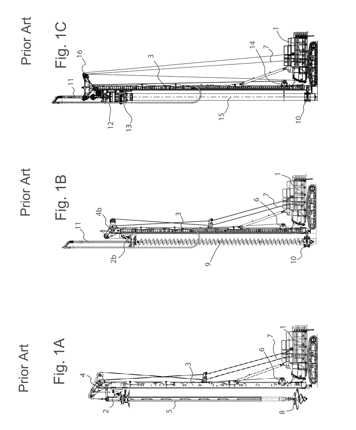
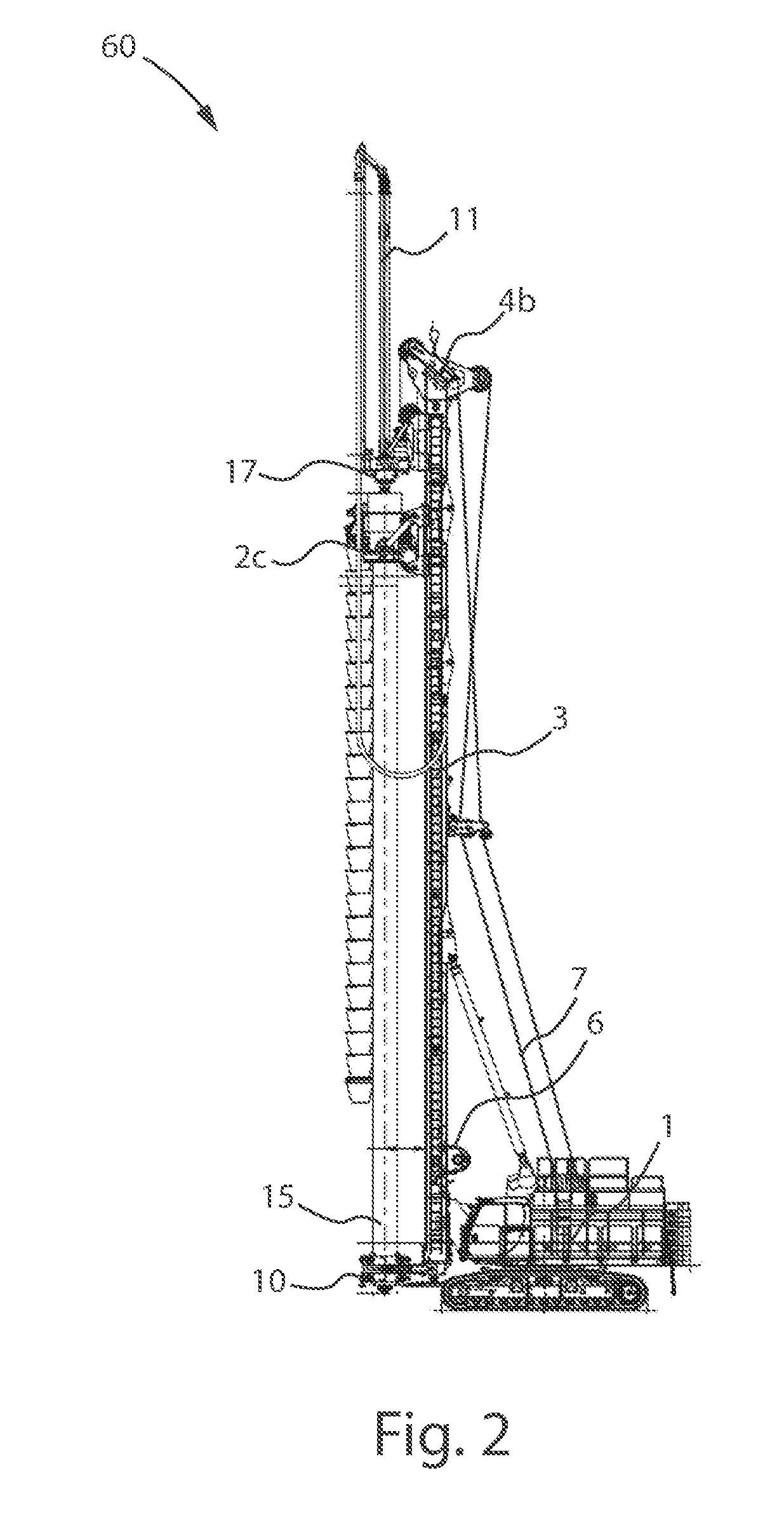
[0079]With reference to the figures, a modular assembly for handling excavating equipment for excavating machines for making excavated piles is shown.

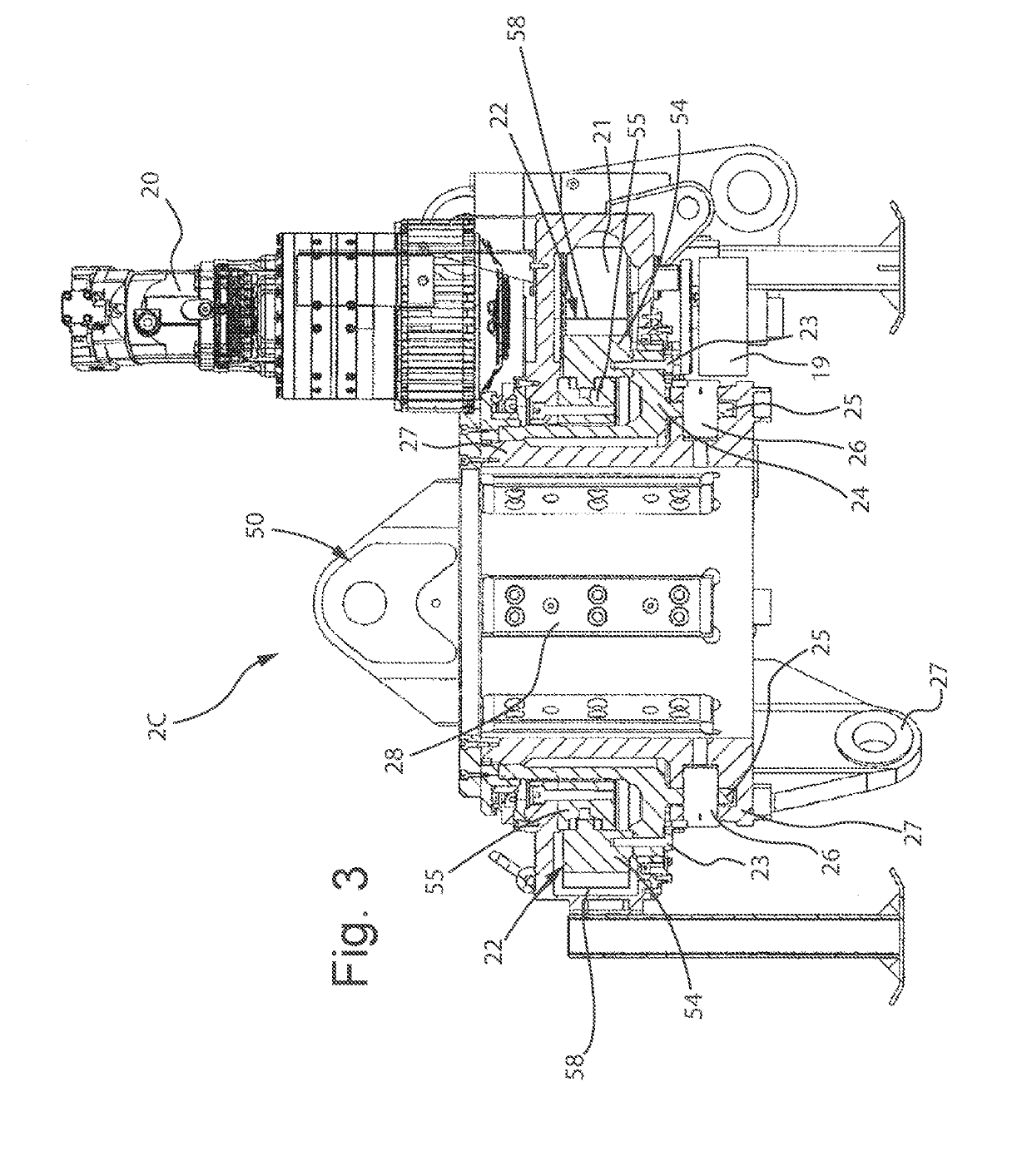
[0080]Such a modular handling assembly comprises a first rotating table or rotary 2c, a plurality of accessories 27, 29, 31 able to be associated with the first rotating table 2c so it can be selectively coupled to a telescopic Kelly rod or Kelly rod 5, or with a continuous excavating propeller 9, 9b, 9c or with a casing and excavating pipe 15,15b and 15c, and a second rotating table or rotary 17 adapted for being coupled with a continuous excavating propeller 9, 9b, 9c.

[0081]The modular handling assembly, according to the present invention, can be set up in a different manner by equipping the first rotating table 2c with the accessories adapted for making it suitable for coupling with the different excavating equipment.

[0082]FIGS. 3, 4 and 5 show the first rotary 2c in LDP, CFA and CSP configuration, respectively. The first rotating ...


PUM


Abstract

A modular assembly for handling excavating equipment is disclosed. The assembly includes a first rotating table having a main body; one or more motors, each having a pinion, associated with the main body; a bearing having a fixed ring constrained to the main body and a movable ring that is coaxial and rotatable with respect to the fixed ring; a dragging sleeve integrally coupled with the movable ring coaxially to the bearing; a ring gear integrally and coaxially coupled with the dragging sleeve to engage with the pinion and be moved in rotation by the motors rotating integrally with the dragging sleeve and integrally with the movable ring. The assembly also has a second rotating table adapted to be coupled to a continuous excavating propeller; a plurality of accessories associated with the first rotating table so it can be coupled to a telescopic Kelly rod or to a continuous excavating propeller or to a casing and excavating pipe.

Description

CROSS-REFERENCE TO RELATED APPLICATION[0001]This application claims the benefit of Italian Patent Application No. 102017000024727 filed Mar. 6, 2017, the contents of which are incorporated herein by reference.FIELD OF THE INVENTION[0002]The present invention refers to a modular assembly for handling excavating equipment for excavating machines, to an excavating machine, and to a method for converting the excavating configuration of an excavating machine.BACKGROUND OF THE INVENTION[0003]In particular, the present invention is particularly useful in the field of excavating machines for making piles for foundations.[0004]The technology for making piles of large diameter for foundations provides three main excavation methods, corresponding to three different excavating set-ups or configurations of the excavating machine.[0005]The first method is LDP (large diameter pile) or drilled pile with telescopic Kelly rod or Kelly rod to which a tool of the bucket or drill type can be applied.[00...

Claims


Application Information

Patent Timeline
Patent Type & Authority Patents(United States)
IPC IPC(8): E02D7/00E02D5/36E21B7/02E21B7/20E02D7/18E02D7/30E21B7/00
CPCE02D7/30E21B7/005E21B7/021E21B7/201E02D5/36E02D7/00E02D7/18E21B7/027E21B7/002E02D2250/0038
Inventor DITILLO, ALESSANDROBISERNA, EZIO
Owner SOILMEC
Why Eureka
Try Eureka