Microfluidic apparatus and method

a technology of microfluidic apparatus and cassette, which is applied in the direction of fluid controllers, chemistry apparatus and processes, laboratory glassware, etc., can solve the problems of cassette contact, reducing the effectiveness of such reagents, and affecting the efficiency of microfluidic agents, etc., to achieve simple, quick and cost-effective effect, easy and quick manufacturing

Pending Publication Date: 2022-06-02
QUANTUMDX GROUP
View PDF0 Cites 0 Cited by
  • Summary
  • Abstract
  • Description
  • Claims
  • Application Information

AI Technical Summary

Benefits of technology

[0045]In accordance with certain embodiments of the invention, a microfluidic diagnostic system is provided comprising a microfluidic cassette and a microfluidic diagnostic device comprising at least one actuator adapted to break the seal of the chamber of the microfluidic cassette. Certain embodiments of the invention provide a system that requires fewer user steps to bring the cassette into operation. Embodiments of the system provide an automated means for actuating the seal.
[0046]In accordance with certain embodiments of the invention, the at least one actuator comprises an aperture shaped to receive the microfluidic cassette body. Certain embodiments can provide an arrangement whereby the cassette body is passed through an aperture and the shape of the aperture contacting the cassette body causes the seal to be actuated. Certain embodiments of the invention provide a simple mechanical means of actuating the seal.
[0047]In accordance with certain embodiments of the invention, the at least one actuator comprises a moveable actuating member. Certain embodiments of the invention provide a controllable mechanical member that can be used to actuate the seal in situ. Certain embodiments of the invention provide a precise and controllable means of seal actuation that can be fully automated.
[0048]In accordance with certain embodiments of the invention, the at least one actuator comprises a source of heat or a source of directional light. Certain embodiments of the invention provide a controllable and automated means of actuating the seal that may not require physical contact with the cassette to actuate the seal.
[0049]In accordance with certain embodiments of the invention, a reagent containing insert for a microfluidic cassette body is provided. Certain embodiments of the invention provide an insert including a seal which is breakable in situ in the cassette body. Certain embodiments of the invention provide an insert that may be easy and quick to manufacture and can be sealed at the time of manufacture to prevent fluid or other external materials from contacting and potentially degrading the reagent. Certain embodiments of the invention provide an insert that can be sealed within a cassette until a time of use.
[0050]In accordance with certain embodiments of the invention, a method of manufacturing a microfluidic cassette is provided. Certain embodiments of the invention provide a simple, quick and cost-effective method of manufacturing an improved microfluidic cassette.

Problems solved by technology

Moisture can be a problem when dried or wet reagents are used.
However, moisture is a particular problem when dried (or lyophilised) reagents are used because such reagents are hydrophilic and even small amounts of moisture can interact with and potentially reduce the effectiveness of such reagents.
However, in this arrangement even if the microfluidic cassette is sealed during manufacture, moisture from the atmosphere or vapour arising from fluids deliberately stored in the cassette can contact and degrade the reagent over time.
This can reduce the effectiveness of diagnostic tests performed using the cassette and / or reduce the storage life of the cassette.
However, it suffers from similar disadvantages as discussed above regarding depositing reagent directly in fluid flow channels, namely that the dried substance is exposed inside the cassette after cup insertion and will tend to degrade over time, particularly as a result of moisture / vapour.
This arrangement can also result in a “dead zone” of dried substance that is retained on the carrier element after fluid flow has occurred or can require a smaller amount of dried substance to be used to reduce this effect.
Further, even if the removeable lid or seal is removed automatically during insertion, dried chemicals in the container are still exposed to the local environment immediately before the container is introduced into the cassette, thereby risking degradation of the reagent.
Further, prior to inserting the container into the cassette, the aperture in the cassette (and, as a result, the fluid flow channel) is exposed to moisture the local environment or otherwise requires an additional and potentially complex sealing mechanism to prevent moisture and other contaminants from entering the cassette prior to container insertion.

Method used


Image

  • Microfluidic apparatus and method
  • Microfluidic apparatus and method
  • Microfluidic apparatus and method

Examples


Embodiment Construction

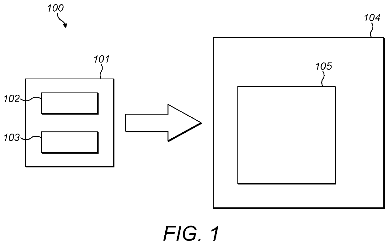
[0067]FIG. 1 provides a simplified schematic representation of a microfluidic diagnostic system 100 in accordance with certain embodiments of the invention. The system 100 comprises a microfluidic cassette 101 comprising a microfluidic cassette body 102 and at least one chamber 103. The cassette 101 may substantially correspond to the cassette described in more detail herein and in particular with reference to FIG. 2.

[0068]The system 100 further comprises a microfluidic diagnostic device 104 adapted to receive the cassette 101. The diagnostic device 104 may comprise a cassette receiving region that allows the cassette 101 to be inserted into and interact with the diagnostic device 104. The diagnostic device 104 may further comprise components that enable it to interact with the cassette 101 and perform diagnostic tests on a fluid sample contained in the cassette. For example, the diagnostic device 104 may comprise one or more diagnostic sensing and / or imaging components for conducti...


PUM


Abstract

A microfluidic cassette has a microfluidic cassette body having at least one fluid flow channel and at least one chamber containing reagent. The chamber has a seal to prevent fluid from entering the chamber. The seal is breakable in situ in the cassette body. The cassette body and the chamber are configured such that when the seal is broken, the reagent is exposed to fluid flow in the channel.

Description

PRIORITY AND CROSS REFERENCE TO RELATED APPLICATIONS[0001]This application is the U.S. National Phase Application under 35 U.S.C. § 371 of International Application No. PCT / GB2019 / 053361, filed Nov. 28, 2019, designating the U.S. and published in English as WO 2020 / 109797 A1 on Jun. 4, 2020, which claims the benefit of Great Britain Application No. GB 1819415.9, filed Nov. 29, 2018. Any and all applications for which a foreign or a domestic priority is claimed is / are identified in the Application Data Sheet filed herewith and is / are hereby incorporated by reference in their entireties under 37 C.F.R. § 1.57.TECHNICAL FIELD[0002]The present invention relates to microfluidic devices and more particularly to microfluidic cassettes used with such devices.BACKGROUND[0003]Microfluidic diagnostic devices can provide rapid point of care diagnosis of health conditions based on fluid samples provided by a patient. Such devices may comprise diagnostic electronics or other components that enabl...

Claims


Application Information

Patent Timeline
Patent Type & Authority Applications(United States)
IPC IPC(8): B01L3/00B01L7/00
CPCB01L3/502715B01L7/52B01L2200/04B01L2300/087B01L2200/16B01L2300/0877B01L2200/0689B01L3/5027B01L2300/044B01L2300/0672B01L2400/0677B01L2200/141
Inventor WILLSHARE, THOMAS MICHAELMADADI, HOJJATBENNETT, JAMESSCULLY, PHILIP
Owner QUANTUMDX GROUP
Why Eureka
Try Eureka