Optical sensor arrangement

a technology of optical sensors and optical openings, applied in the direction of optical radiation measurement, pulse technique, instruments, etc., can solve the problem of reducing the visibility of the opening

Active Publication Date: 2019-09-24
AMS AG
View PDF7 Cites 6 Cited by
  • Summary
  • Abstract
  • Description
  • Claims
  • Application Information

AI Technical Summary

Benefits of technology

[0004]According to the improved concept, a first cover layer of an optical sensor arrangement has two openings or apertures located above an emitting device and a detection device, respectively. Depending on the optical properties of the first cover layer, at least one of the openings is covered with another cover layer having optical properties that are adapted to the optical properties of first cover layer. In particular, the other cover layer may render the respective opening effectively invisible to the human eye or reduce the visibility of the opening. In other words, the respective opening is camouflaged or disguised by adapting said optical properties. Since two openings or apertures are used, a distance or separation between the emitting device and the detection device may be increased to reduce optical crosstalk.
[0014]The cover may for example be designed to protect the emitting device, the detection device and / or the package from external influences as for example dust particles, mechanical damage, humidity or the like.

Problems solved by technology

In particular, the other cover layer may render the respective opening effectively invisible to the human eye or reduce the visibility of the opening.

Method used


Image

  • Optical sensor arrangement
  • Optical sensor arrangement

Examples


Embodiment Construction

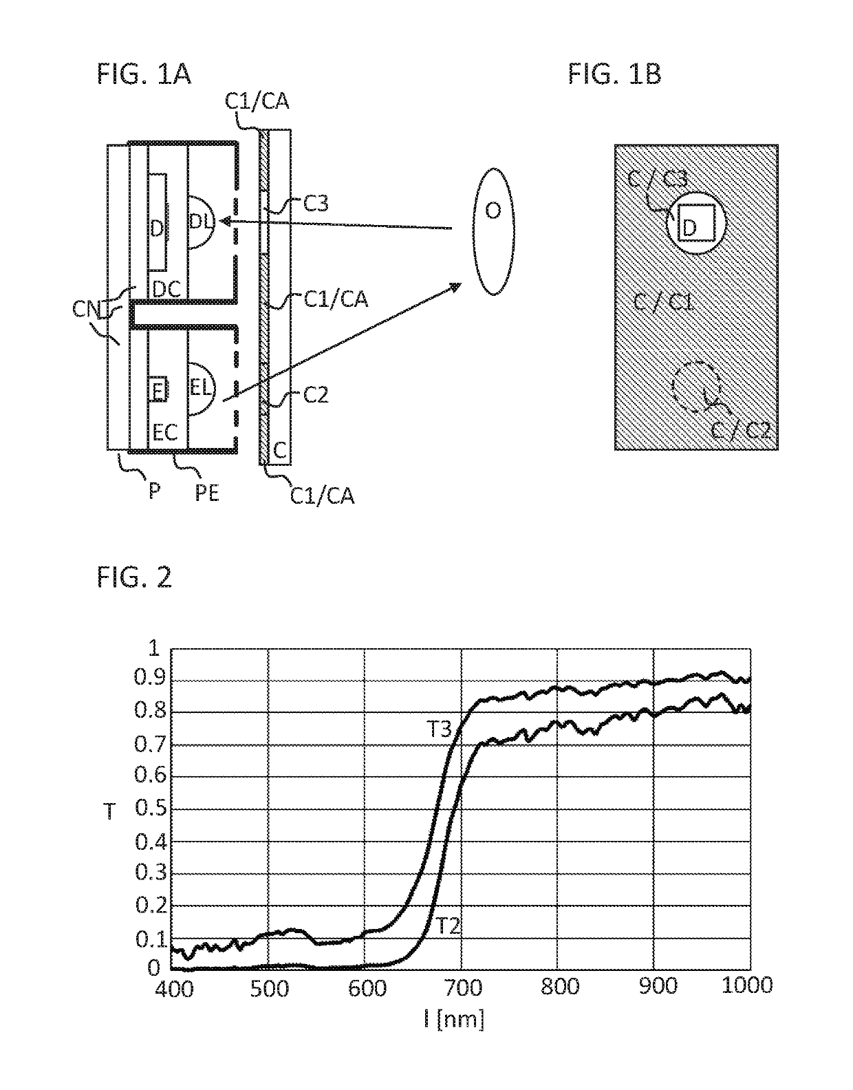
[0057]FIG. 1A shows a cross section of an exemplary implementation of an optical sensor arrangement according to the improved concept.

[0058]The sensor arrangement comprises a sensor package P with a contacting arrangement CN and a package encasement PE. The sensor arrangement further comprises an emitting device E and a detection device D mounted on the contacting arrangement CN. In particular, the emitting device E and the detection device D are arranged on a first plane of the sensor arrangement. The emitting device E and the detection device D may be electrically and / or mechanically connected to the contacting arrangement CN. The emitting device E is embedded within an emitter casting EC of the sensor arrangement and the detection device D is embedded within a detector casting DC of the sensor arrangement. The sensor arrangement also comprises an emitter lens EL mounted on the emitter casting EC above the emitting device E and a detector lens DL mounted on the detector casting DC...


PUM


Abstract

An optical sensor arrangement comprises an emitting device (E) and a detection device (D) configured to emit and detect, respectively, electromagnetic radiation and a cover (C) arranged to cover the emitting and the detection device (E, D). The sensor arrangement comprises a first cover layer (C1) partially covering an inner surface of the cover (C) and having a first and a second opening located above the emitting and the detection device (E, D), respectively. The sensor arrangement comprises a second and a third cover layer (C2, C3) covering the inner surface at areas of the first and the second opening. A reflection and / or an absorption characteristics of at least one of the second and third cover layer (C2, C3) is adapted to a reflection and / or an absorption characteristics of the first cover layer (C1) for incident light within the specified spectrum.

Description

BACKGROUND OF THE INVENTION[0001]The present invention relates to an optical sensor arrangement, and a proximity sensor arrangement and a gesture sensor arrangement.[0002]Optical proximity and gesture sensors may be used widely in modern smart phones. Optical proximity or gesture sensors may be implemented as active sensors being able to detect the presence and movement, respectively, of nearby objects without physical contact. An optical proximity or gesture sensor may emit light, for example visible or infrared light, and detect the light returning after being reflected by an object. Since the light emitting device and the detection device may be positioned adjacent to each other and the light may have to pass through a cover glass or cover plastic for example with ink printed on it, light may get reflected by the cover or scattered by the ink and consequently be detected without having left the sensor arrangement and reached an object. This phenomenon is denoted as optical crosst...

Claims


Application Information

Patent Timeline
Patent Type & Authority Patents(United States)
IPC IPC(8): G01J1/02G01S7/481G01S17/02G06F3/03H03K17/94G06F3/01G01V8/14G01V8/12G01S17/04
CPCG01S17/026G01J1/0271G01V8/12H03K17/941G06F3/0304G01V8/14G01S7/4813G06F3/017H03K2217/94108G01S17/04
Inventor WANG, YU
Owner AMS AG
Why Eureka
Try Eureka