Electrical energy generating brushless DC motor

a brushless dc motor and electric energy technology, applied in the direction of engine-driven generator control, electric generator control, transportation and packaging, etc., can solve the problem that their maximum potential has not yet been fully realized, and achieve the effect of limiting the amount of back-emf generated in the motor, maximizing efficiency, and increasing electrical energy

Active Publication Date: 2019-10-01
NY THOU M
View PDF24 Cites 3 Cited by
  • Summary
  • Abstract
  • Description
  • Claims
  • Application Information

AI Technical Summary

Benefits of technology

[0007]The present disclosure provides brushless direct current (BLDC) motors that generate electrical energy while operating as a motor. In certain embodiments, the BLDC motor of the present disclosure includes a dual purpose stator assembly for producing torque in the rotor and for generating electrical energy output for load consumption. The stator assembly is designed, in one embodiment, so that the stator poles can accommodate both windings and stator windings can be structured to maximize efficiency. For example, the stator winding assembly of one embodiment of the present disclosure is designed so that the torque producing segment of the windings are wound and placed farther away from the air gap and flux density of the permanent magnet rotor. Doing so allows less magnetic field density or lines of force to cut across the windings, thus limiting the amount of back-EMF generated in the motor. On the other hand, the winding segment for generating electrical energy can be placed at close proximity to the air gap where the flux density is strongest to allow for capturing the maximum magnetic field possible for generating electrical output. A prototype of one embodiment demonstrated an efficiency of 90-95%. Thus BLDC motors according to the present disclosure are more efficient than the conventional motor-generator set which operate on a typical efficiency range of 70% to 80%. Further, when the motor is operating under rated load, the generator feature advantageously produces at least 50% of electrical output of the input supply. The lighter the load being pressed upon the motor, the more electrical energy it can generate.
[0010]As noted earlier, conventional BLDC motors also generate electrical energy known as back electromotive force (back-EMF), namely because upon being generated, the electrical energy travels in the opposite direction and opposes the supply voltages. In the area of motor efficiency, back-EMF is considered as a constraint or challenge in the art, in part because to overcome the back-EMF value, more input energy is required to drive the motor, until equilibrium is reached. Because the conventional motors generate back EMF, it is one of the major power factor considerations during the design of a typical motor. Thus, to increase efficiency, the dual purpose stator assembly of the present disclosure can be designed to reduce the level of back-EMF being generated during motor operation. To this end, in certain embodiments, the stator assembly includes poles of sufficient length so that the energizer segment of the stator pole is wound and placed sufficiently far away from the air gap and the rotor's magnetic flux density. Placing the energizer windings as far away as possible from the air gap and flux density limits the amount of the rotor's magnetic field from cutting across the energizer coil windings, thereby limiting the amount of back-EMF from generating in the energizer windings. Thus, with less back-EMF to overcome, a lesser amount of energy from the supply input source is drawn to drive the motor. To this end, the length of stator poles can be optimized to accommodate both the inducer and energizer windings to allow for the motor's dual purpose functions to operate efficiently.
[0012]As noted, a novel feature of the motors of the present disclosure is their ability to generate electrical energy. Consistent with the operating principles of the conventional AC generator, the amount of voltage induced in the inducer windings depends on a few factors: the strength of the rotor's magnetic field, the speed of which the magnetic field is moving across the windings, resistance and reactive power factors, and the number of the inducer coil winding turns placed in relative motion of the rotor's magnetic field. The greater the value to generate, the more the inducer coil winding turns are needed. The lesser the value of voltage to be generated, the smaller the number of inducer coil winding turns needed. However, it should be noted that to generate electrical energy in a conventional power generator, a separate prime moving force is often required to rotate the magnetic fields necessary to create electrical energy through the generator's stator windings. The prime moving force is usually furnished by a combustion engine, a turbine, or an electric motor.
[0013]On the other hand, the motors of the present disclosure do not require an outside prime moving force or mechanical coupling because both the motor and generator features share the same stator assembly and permanent magnet rotor. Thus, both motor and generator features benefit from the same rotating magnetic field for torque and electrical energy generation. In other words, while a motor consumes electrical energy input for normal motor operation, the motor generates electrical energy simultaneously. Based on a working prototype of one embodiment of the present disclosure, up to 95% of the motor's power input was generated when the motor was not loaded (rotor shaft not connected to a load). When the motor is operating under rated load, 50% or more of the motor's power input can be generated by the inducer winding segments. The lighter the load of the motor, the more electrical energy the motors of the present disclosure can generate.
[0014]To this end, the ability to generate electrical energy while in active motoring function offers unique and significant advantages and advancements to modern electric vehicles. Today's electric vehicles are limited by their battery capacity and drive range. Thus, the motors of the present disclosure advantageously address these limitations by having the ability to serve effectively as a powertrain and an electrical energy generator in electric vehicles. In other words, while propelling the vehicle drive wheels, the electrical energy it generates simultaneously can be routed to the vehicle's battery bank or energy storage system, thus prolonging the battery capacity of the vehicle and resulting in an extended drive range.

Problems solved by technology

However, despite their amazing capabilities and contributions, a deeper examination of their operating features reveals that their maximum potential has yet to be fully realized.

Method used


Image

  • Electrical energy generating brushless DC motor
  • Electrical energy generating brushless DC motor
  • Electrical energy generating brushless DC motor

Examples


Embodiment Construction

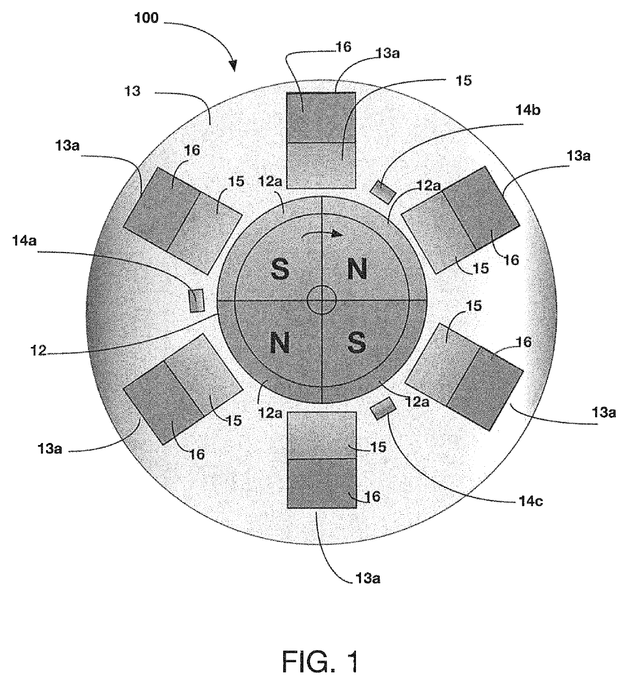
[0025]FIG. 1 depicts a BLDC motor 100, according to one embodiment. BLDC motor 100 includes a permanent magnet rotor 12, a stator core assembly 13, which includes a plurality of dual purpose stator winding assemblies 13a configured so that one segment of each stator pole windings 16 produces torque in the rotor 12 and the other segment of each stator pole windings 15 generates electrical energy output. The permanent magnet rotor 12 can be of various poles 12a (e.g., alternating N and S as shown). Thus the present embodiment can be operable using a single-phase, or multiple-phase winding configurations. These various winding phase configurations are applicable for both producing torque in the rotor and for generating electrical energy output. For the purpose of illustration, the BLDC motor 100 being described herein is an inrunner BLDC motor, although the motor can also be of outrunner configuration (not shown). For commutation, magnetic Hall Effect sensors, 14a, b, c are provided. T...


PUM


Abstract

A brushless direct current (BLDC) motor that generates electrical energy (AC voltage) while operating as a motor. The motor is configured with a dual purpose stator assembly wherein one segment of the stator assembly includes coil windings to produce the rotary force (torque) in the rotor and the other segment of the stator assembly includes coil windings to generate electrical energy. The stator windings for producing torque are electrically connected through commutation control circuitry to a DC supply source, and the stator windings for generating electrical energy are connected to a load or to an energy storage system. Thus, the embodiment offers a novel means for generating electrical energy in the conventional BLDC motors. Because the motor can generate electrical energy while operating as a motor, it can effectively serve as a powertrain in electric vehicles, whereby the electrical energy it generates can be used to extend the vehicles' drive range.

Description

BACKGROUND[0001]The present disclosure relates to electric motors and generators or electrical power generating motors. In particular, the present disclosure relates to a sensor or sensorless brushless DC motor configured to generate AC electrical output while operating as a motor. Accordingly, the novel characteristics of the present disclosure include having a dual purpose stator assembly for producing torque in the rotor and for generating electrical energy output for load consumption. Thus, the embodiment offers a novel means for energy generation in BLDC motors. Further, its novel structural design as demonstrated by a prototype of a practical embodiment of the present disclosure allows it to achieve an efficiency level of 90-95%. This amount is greater than the conventional motor-generator (MG) set which operates on a 70% to 80% efficiency range. In addition, its dual functionality also allows it to effectively serve as powertrain in electric vehicles, while also adding signif...

Claims


Application Information

Patent Timeline
Patent Type & Authority Patents(United States)
IPC IPC(8): H02K53/00H02P9/00H02K11/215B60L50/12B60L50/13
CPCB60L50/12H02K53/00H02K11/215Y02T10/70Y02T10/7077Y10S74/09Y02T10/646Y02T10/641H02P9/00Y02T10/64Y02T10/7072
Inventor NY, THOU M.
Owner NY THOU M
Why Eureka
Try Eureka