
Damping hinge

a hinge and hinge body technology, applied in the field of hinges, can solve the problems of limited structure strength, lack of internal dampers for hinges, and high production costs, and achieve the effect of reducing size and production costs

Active Publication Date: 2019-10-15
FOXLINK IMAGE TECH
View PDF18 Cites 3 Cited by
  • Summary
  • Abstract
  • Description
  • Claims
  • Application Information

AI Technical Summary

Benefits of technology

[0006]As described above, in the operation process of the damping hinge in this invention, during the time that the revolving part rotates between the first and the second positions, the engaging portion of the first enforcement frame is not contacting with the actuating portion and thus the motion of the revolving part is undamped; and during the time that the revolving part rotates between the second and the third positions, the engaging portion of the first enforcement frame pressing the actuating portion continuously to damp the motion of the revolving part. Therefore, the damping hinge in this invention has an inner damper to reduce the size and the production cost.

Problems solved by technology

Limited to the structure strength, the plastic hinge mostly lacks of an internal damper and needs to assemble with an external damper, and thus it is commonly used in low-end products.
Therefore, the iron casting hinge can be used in both high-end and low-end products, but it also has some disadvantages such as being expensive in production cost, larger in size and heavier in its weight.
Therefore, a conventional hinge needs extra space to assemble due to its size, more expensive in production cost and heavier in its weight.

Method used


Image

  • Damping hinge
  • Damping hinge
  • Damping hinge

Examples


Embodiment Construction

[0017]In order to describe the technical contents, structural features, purpose to be achieved and the effectiveness of the present invention, the detailed description is given with schema below.

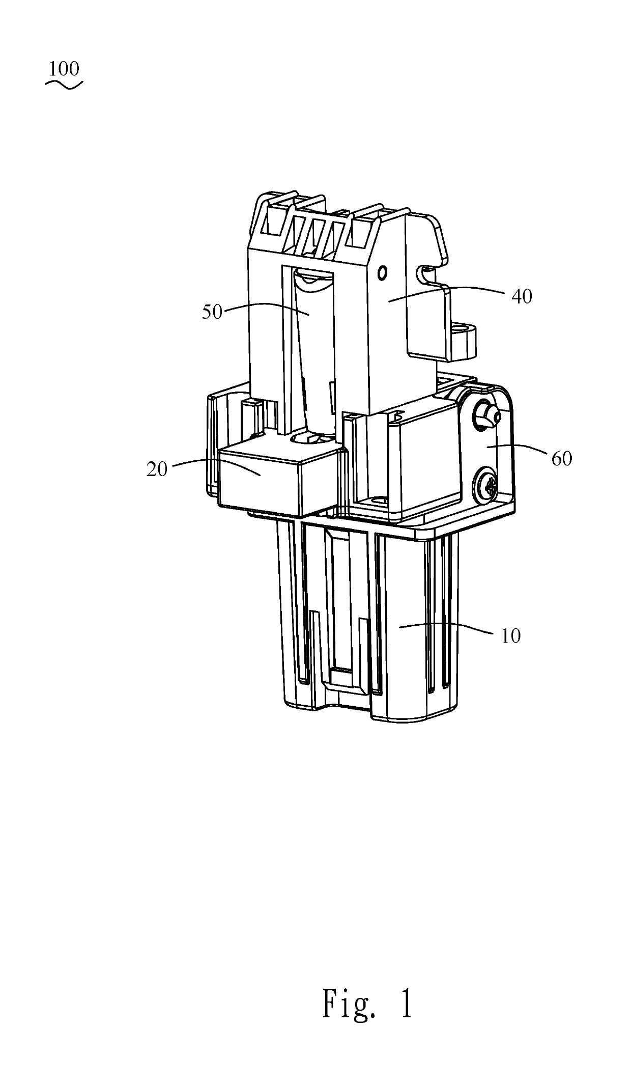
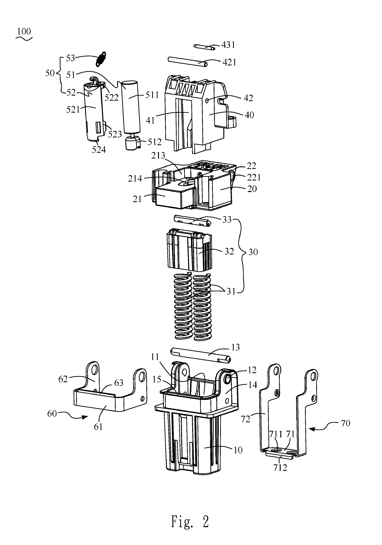
[0018]Referring to FIG. 1 and FIG. 2, the damping hinge 100 in the present invention is designed for being used in a scanner (not shown) which mainly consists of a scanner body (not shown) and an upper cover (not shown) being free to swing open and close to the scanner body. The damping hinge 100 comprises a first joining part 10, a revolving part 20, a supporting module 30, a second joining part 40, a damping module 50 and a first enforcement frame 60.

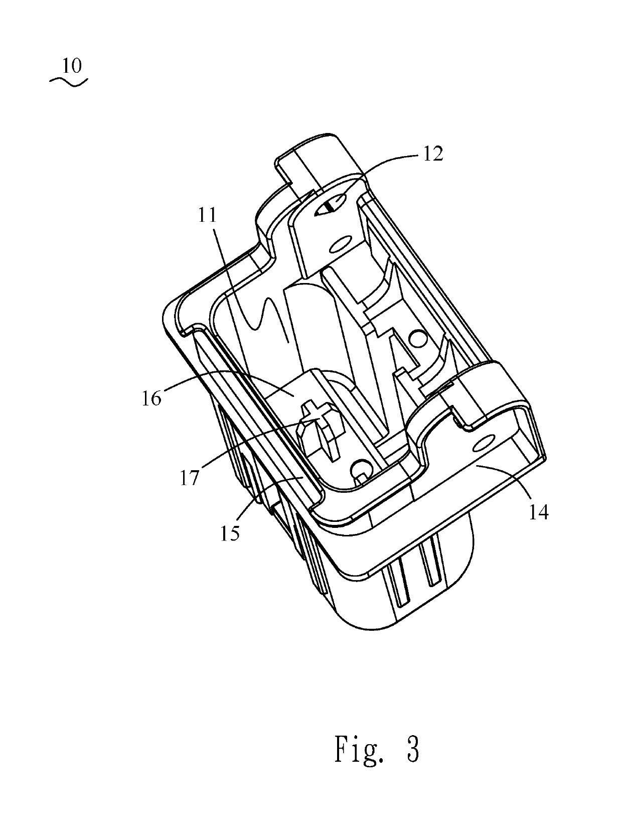
[0019]Referring to FIG. 2 and FIG. 3, The first joining part 10 comprises an accommodating space 11 and two first revolving holes 12 located on one side surface of the upper portion of the first joining part 10 for holding a revolving pin 13 within. The side surface of the upper portion of the first joining part 10 further comprises a first ho...


PUM


Abstract

A damping hinge includes a first joining part; a revolving part pivotably connected to the first joining part and being capable of revolving among a first position, a second position and a third position; a supporting module arranged within the first joining part for pressing the revolving part to keep the revolving part and the first joining part staying in a relative position; a second joining part fastened to the revolving part for connecting the upper cover; a first enforcement frame arranged on the first joining part; and a damping module including a damper holder pivotably connected to the second joining part, a damper consisting of a damper core fastened on the damper holder as a fixed end and an actuating portion as a free end being able to move up and down, a damper spring connected between the second joining part and the damper holder.

Description

BACKGROUND OF THE INVENTION1. Field of the Invention[0001]This invention relates to a hinge, particularly a damping hinge.2. The Related Art[0002]The scanner, copier, printer and the fax machine are widely used in a modern office, and each of them has a hinge and a damper that holds the upper cover and the main body of the machine together. Said hinge mainly comes in two types, the plastic hinge with a spring and the iron casting hinge. Limited to the structure strength, the plastic hinge mostly lacks of an internal damper and needs to assemble with an external damper, and thus it is commonly used in low-end products. On the other hand, the iron casting hinge is made of iron parts and being secured with rivets, so it has larger inner space for assembling an inner damper and better structure strength. Therefore, the iron casting hinge can be used in both high-end and low-end products, but it also has some disadvantages such as being expensive in production cost, larger in size and he...

Claims


Application Information

Patent Timeline
Patent Type & Authority Patents(United States)
IPC IPC(8): E05F1/08E05D3/02E05F3/20E05D11/00H04N1/00E05D11/06
CPCE05D3/02E05F1/1261E05F3/20E05F5/02E05Y2201/212E05Y2201/264E05Y2201/412E05Y2201/638E05Y2900/60E05Y2900/608H04N1/00554H04N1/00976E05D11/00E05D11/06
Inventor FANG, JING HUALU, PEI CHUN
Owner FOXLINK IMAGE TECH
Learn More