Hydroelectric power generation device for operation with water flow of sanitary piping

a technology of hydroelectric power generation and sanitary piping, which is applied in the direction of sustainable buildings, mechanical equipment, machines/engines, etc., can solve the problems of undesired oscillation, complicated assembly, and difficulty in ensuring the free flow of electric leaking electrical wires, so as to improve the advantageous position of products and increase the product yield of the present invention

Active Publication Date: 2019-10-15
YANG SHUN MING
View PDF30 Cites 4 Cited by
  • Summary
  • Abstract
  • Description
  • Claims
  • Application Information

AI Technical Summary

Benefits of technology

[0018]With the structural arrangement described above, the present invention provides advantages that are brief described as follows. The axle of the power generation module of the present invention is supported by the bearing and the sleeve so as to correct the position of the axle in the rotation thereof, whereby the stability of the power generation module could be kept during the operation thereof. Further, one single sleeve is sufficient for correction of the axle, so that assembly does not necessarily go through a complicated process required in the prior art and thus product yield of the present invention could be increased so as to improve the advantageous position of product of the present invention.

Problems solved by technology

However, the bathroom installations are often in a damp environment and it is generally difficult to ensure the electrical wires so connected or buried are free of electric leaking issues.
In such a known device, the assembly is complicated because a large number of bushings are used to keep a central axle in a proper position.
The bushings may also cause undesired oscillation during the operation of the power generation module.

Method used


Image

  • Hydroelectric power generation device for operation with water flow of sanitary piping
  • Hydroelectric power generation device for operation with water flow of sanitary piping
  • Hydroelectric power generation device for operation with water flow of sanitary piping

Examples


Embodiment Construction

[0027]The following descriptions are exemplary embodiments only, and are not intended to limit the scope, applicability or configuration of the invention in any way. Rather, the following description provides a convenient illustration for implementing exemplary embodiments of the invention. Various changes to the described embodiments may be made in the function and arrangement of the elements described without departing from the scope of the invention as set forth in the appended claims.

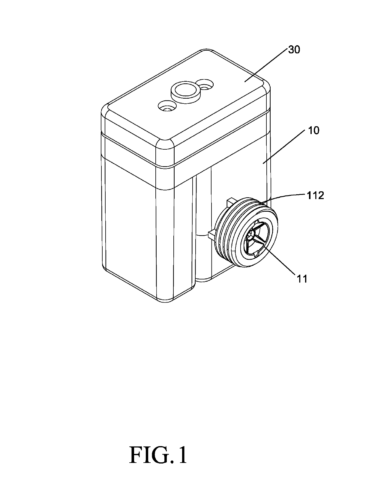
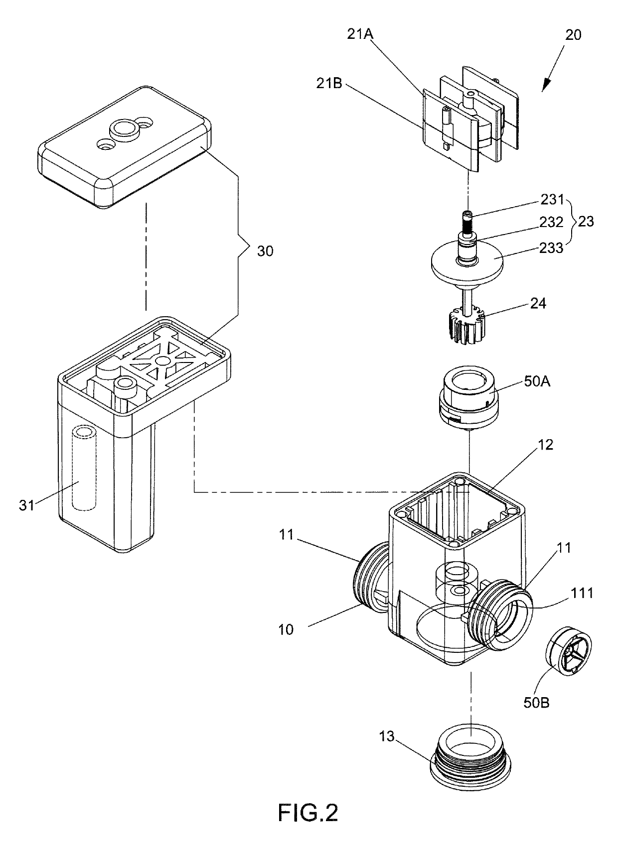
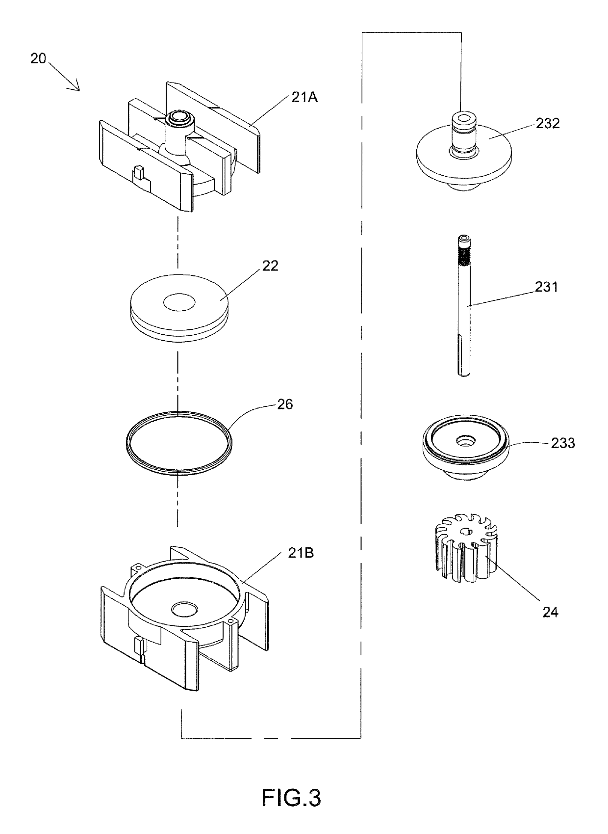
[0028]Referring to FIGS. 1-6, an improved structure of a hydroelectric power generation device according to the present invention generally comprises: a functional main body 10, a power generation module 20, and a battery assembly 30.

[0029]Referring to FIGS. 1-6, the functional main body 10 comprises a hollow casing structure. In a preferred embodiment, the functional main body 10 is selectively made of a plastic material. The functional main body 10 is provided, on each of the two opposites sides t...


PUM


Abstract

A hydroelectric power generation device is structure to utilize water flowing to generate electrical power that could be supplied to a bathroom installation and is generally made up of a functional main body, a battery assembly, and a power generation module. The functional main body has two opposite sides each including a mounting end formed thereon. The functional main body forms therein a receiving chamber. The power generation module includes a stator and a rotor. The rotor is coupled, in a manner of being rotatable, to an axle, which is coupled to a vane wheel. Water flowing into the device drives the vane wheel and the rotor to rotate simultaneously so that magnetic interaction between the rotor and the stator generates electrical power that is supplied to a sensor controlling supply of water flow. A sleeve is fit over the axle for correcting and stably supporting the axle in rotation.

Description

(A) TECHNICAL FIELD OF THE INVENTION[0001]The present invention relates generally to an improved structure of a hydroelectric power generation device, and more particularly to a hydroelectric power generation device that comprises a sleeve for supporting and correcting a central position of an axle so as to keep the axle rotating at the central position, without undesired oscillation or wobbling, during the rotation of the hydroelectric power generation device, and also allowing the axle to be slightly elongated to improve the performance of power generation.(B) DESCRIPTION OF THE PRIOR ART[0002]Bathroom installations that are currently available, in addition to basic sanitary functions, are generally designed to meet specific requirements. Taking urinals as an example, the urinals are often provided with an auto-flush function, which is achieved with an infrared sensor that detects if a user is approaching or leaving the urinal. After the user has finished with urination, the infra...

Claims


Application Information

Patent Timeline
Patent Type & Authority Patents(United States)
IPC IPC(8): F03B11/04H02K7/18H02K7/08H02K5/10H02K11/00F03B3/00F03B3/12
CPCF03B13/00F05B2220/20F05B2220/602F05B2260/42H02K5/1732H02K7/1823H02K11/0094Y02B10/50F03B3/128H02K5/10H02K7/085
Inventor YANG, SHUN-MING
Owner YANG SHUN MING
Why Eureka
Try Eureka