Method and an apparatus for determining a spectrum

a spectrum and apparatus technology, applied in particle spectrometer methods, instruments, material analysis, etc., can solve the problem of limited resolution of measured spectra, and achieve the effect of high data collection rate and better resolution

Active Publication Date: 2019-10-15
TOFWERK
View PDF8 Cites 0 Cited by
  • Summary
  • Abstract
  • Description
  • Claims
  • Application Information

AI Technical Summary

Benefits of technology

[0024]As mentioned already, the cycles are started with different offsets in time as compared to the start of the modulation function they are respectively assigned to. According to the invention, at least one of these offsets has an absolute value different from zero, different from the detection time resolution and different from multiples of the detection time resolution. Due to this at least one of the offsets which has an absolute value which is at the same time different from zero, different from the detection time resolution and different from multiples, i.e. integer multiples of the detection time resolution, the detector signal of all cycles enables to provide a spectrum with an improved resolution. Consequently, the solution according to the invention has the advantage that it enables to determine the spectrum with a better resolution at a high data collection rate.
[0073]Independent of the type spectrum to be determined and independent of the type the apparatus according to the invention is, the apparatus according to the invention preferably comprises a control unit for controlling the modulation unit to divide the sample into assays for which the physical process or chemical process is initiated successively, timed according to the modulation pattern and for controlling the detector to start each cycle with a different offset in time as compared to the start of the modulation function the respective cycle is assigned to. This has the advantage that the apparatus can optimally be controlled.

Problems solved by technology

The disadvantage of these methods and apparatuses is however that the resolution of the measured spectra is limited.

Method used


Image

  • Method and an apparatus for determining a spectrum
  • Method and an apparatus for determining a spectrum

Examples


Embodiment Construction

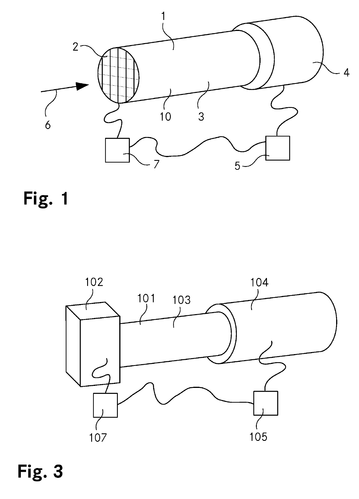
[0081]FIG. 1 shows a schematic view of an apparatus according to the invention in the form of an ion mobility spectrometer 1. This ion mobility spectrometer 1 may be used to execute a method according to the invention in order to determine an ion mobility spectrum.

[0082]The ion mobility spectrometer 1 comprises a modulation unit in the form of an ion gate 2, a drifting region 3, a detector in the form of a mass spectrometer 4 and a calculation unit 5. The drifting region 3 is confined by a tube 10. The ion gate 2 is arranged on an opposite end of the tube 10 than the mass spectrometer 4. The ion gate 2 is of a known type. It comprises a grid of wires. If a voltage with opposite signs is applied to neighbouring wires of the grid, ions of an ion beam 6 are prevented of entering the tube 10. If there is no voltage applied to the wires of the grid, the ions of the ion beam 6 may enter the tube 10. The switching of the ion gate 2 is controlled by a control unit 7. The ion gate 2 may be s...


PUM

PropertyMeasurementUnit
resolution in timeaaaaaaaaaa
timeaaaaaaaaaa
detection time resolutionaaaaaaaaaa

Abstract

The invention relates to a method and an apparatus for determining a spectrum of a sample comprising one or more constituent parts on the basis of a time the one or more constituent parts require to undergo a physical process or chemical process. The spectrum is determined by dividing the sample by a modulation unit into assays for which the physical process or chemical process is initiated successively, timed according to a modulation pattern which is a function composed of N consecutive modulation functions with N being 2 or larger, by measuring with a detector in N consecutive cycles a time when the constituent parts of the sample have completed the physical process or chemical process, wherein in succession of the cycles, each cycle is assigned to a consecutive one of the modulation functions within the modulation pattern, wherein each cycle is started with an offset in time as compared to a start of the modulation function it is assigned to, wherein for each cycle, the offset is different, wherein the detector provides a detector signal providing information on when what number of constituent parts have completed the physical process or chemical process and wherein the detector signal has a detection time resolution, wherein at least one of the offsets has an absolute value different from zero, different from the detection time resolution and different from multiples of the detection time resolution, and by calculating a correlation of the detector signal and the modulation pattern with a calculation unit.

Description

TECHNICAL FIELD[0001]The invention relates to a method and an apparatus for determining a spectrum of a sample comprising one or more constituent parts on the basis of a time the one or more constituent parts require to undergo a physical process or chemical process.BACKGROUND ART[0002]Methods and apparatuses pertaining to the above mentioned technical field are known. US 2009 / 0294647 A1 (Karsten Michelmann) for example describes an ion mobility spectrometer which is coupled to a mass spectrometer and a corresponding measuring method. In this example, the sample comprises ions. A beam of these ions is modulated according to a continuous modulation function, wherein the modulation frequency of the modulation function is varied over a large frequency range. For a measurement, the modulated ion beam is passed through a drifting region, after what the ions are detected with the mass spectrometer serving as detector for the ion mobility spectrometer. In order to obtain the ion mobility s...

Claims


Application Information

Patent Timeline
Patent Type & Authority Patents(United States)
IPC IPC(8): H01J49/00G01N27/62
CPCG01N30/72H01J49/0027H01J49/0036G01N27/623H01J49/0072
Inventor GONIN, MARCTANNER, CHRISTIAN
Owner TOFWERK
Why Eureka
Try Eureka