Lock-up device for torque converter

a torque converter and locking device technology, applied in fluid gearings, couplings, fluid gearings, etc., can solve the problems of affecting the efficiency of the torque converter, and increasing the number of members of the dynamic damper device, so as to achieve the effect of reducing manufacturing cost and simple construction

Active Publication Date: 2019-10-22
EXEDY CORP
View PDF24 Cites 0 Cited by
  • Summary
  • Abstract
  • Description
  • Claims
  • Application Information

AI Technical Summary

Benefits of technology

[0009]It is an object of the present disclosure to produce a dynamic damper device with a simple construction, whereby manufacturing cost can be lowered.
[0012]In this construction, the dynamic damper device is mounted to the outer peripheral part of the output-side plate. Hence, it is not required to perform works such as welding the dynamic damper device to the turbine shell. Hence, the construction and the manufacturing process of the present device can be simplified. Additionally, unlike a well-known device, it is not required to prepare a plate as a separate member fixed to the turbine shell. Hence, cost reduction can be achieved.
[0019]In this construction, the plurality of elastic members are accommodated in the plurality of windows of the first and second inertia rings. Additionally, the end surfaces of each of the plurality of elastic members make contact with those of each of the plurality of windows. Moreover, the restriction part of each of the plurality of windows restricts each of the plurality of elastic members from axially moving.
[0021]In this construction, the plurality of elastic members of the dynamic damper device are coil springs each having a circular-arc shape (so-called arc springs). Hence, a hysteresis torque can be generated in a relatively low rotational speed range. Therefore, fluctuation in rotational speed can be effectively inhibited even in a low rotational speed range.
[0026]In this construction, at least either the plurality of outer peripheral side torsion springs or the plurality of inner peripheral side torsion springs each have a circular-arc shape. Hence, lowering of a stiffness in torsional characteristics and widening of a torsion angle can be achieved.
[0028]As described above, according to the present disclosure, a dynamic damper device for a lock-up device can be realized with a simple construction at a lowered manufacturing cost.

Problems solved by technology

Therefore, its relevant manufacturing process has a large number of steps and is therefore complicate.
Additionally, increase in number of members composing the dynamic damper device is also inevitable, and this hinders cost reduction.

Method used


Image

  • Lock-up device for torque converter
  • Lock-up device for torque converter
  • Lock-up device for torque converter

Examples


example 1

Practical Example 1

[0034][Entire Construction]

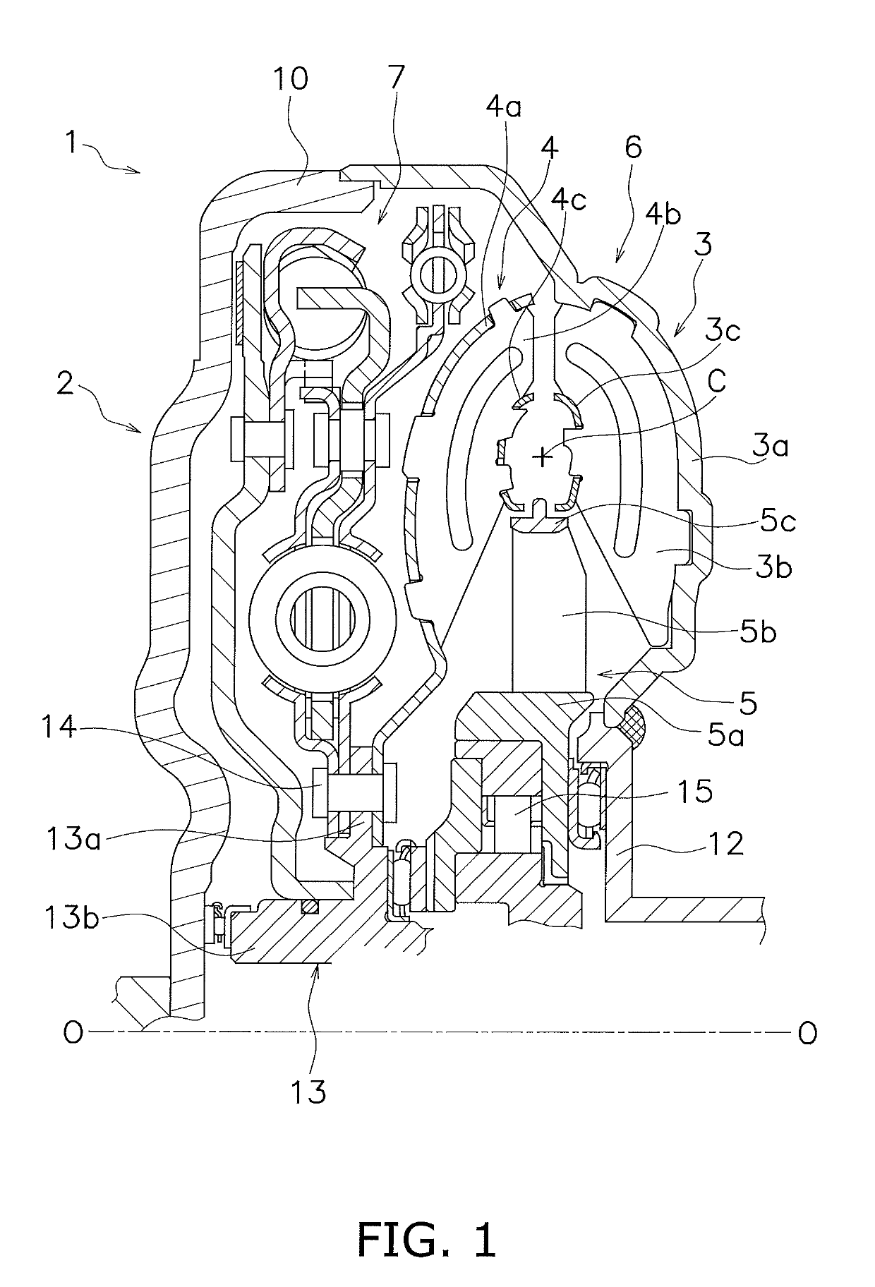
[0035]FIG. 1 shows a torque converter 1 according to an exemplary embodiment of the present disclosure. In FIG. 1, an engine is disposed on the left side, whereas a torque converter and a transmission are disposed on the right side. Line O-O depicted in FIG. 1 is a rotational axis of the torque converter.

[0036]The torque converter 1 is a device configured to transmit a torque from an engine-side crankshaft (not shown in the drawings) to an input shaft of the transmission. The torque converter 1 includes a front cover 2 fixed to an engine-side member, a torque converter body 6 composed of a three types of vane wheels (an impeller 3, a turbine 4 and a stator 5), and a lock-up device 7.

[0037]The front cover 2 is a disc-shaped member and is provided with an outer peripheral tubular part 10 as its outer peripheral part. The outer peripheral tubular part 10 protrudes toward the transmission. The impeller 3 includes an impeller shell 3a, a plur...


PUM


Abstract

A lock-up device includes a clutch portion, an intermediate member, a driven plate, a damper portion and a dynamic damper device. The clutch portion is a portion into which a torque is inputted from a front cover. The intermediate member is a member into which the torque is inputted from the clutch portion. The driven plate is rotatable relatively to the intermediate member and is coupled to a turbine hub. The damper portion elastically couples the intermediate member and the driven plate in a rotational direction. The dynamic damper device is mounted to an outer peripheral part of the driven plate and attenuates fluctuation in a rotational speed.

Description

CROSS-REFERENCE TO RELATED APPLICATIONS[0001]This application is the U.S. National Phase of PCT International Application No. PCT / JP2015 / 051936, filed on Jan. 23, 2015. That application claims priority to Japanese Patent Application. No. 2014-220015, filed Oct. 29, 2014. The contents of both applications are herein incorporated by reference in their entireties.BACKGROUND[0002]Technical Field[0003]The present disclosure relates to a lock-up device, particularly to a lock-up device for a torque converter, which is disposed between a front cover coupled town engine-side member and a turbine of the torque converter.[0004]Background Art[0005]A torque converter is equipped with a lock-up device in order to reduce fuel consumption. The lock-up device is disposed between a front cover and a turbine, and is configured to mechanically couple the front cover and the turbine in order to directly transmit a torque therebetween.[0006]In general, the lock-up device includes a piston and a damper m...

Claims


Application Information

Patent Timeline
Patent Type & Authority Patents(United States)
IPC IPC(8): F16H45/02F16D3/12F16F15/14F16F15/129
CPCF16F15/129F16D3/12F16H45/02F16F15/1421F16H2045/0226F16H2045/0294F16H2045/0205F16H2045/0231F16H2045/0278
Inventor KAWAHARA, YUKI
Owner EXEDY CORP
Why Eureka
Try Eureka