Fluid inspection device

a technology of fluid inspection and inspection device, which is applied in the direction of fluid controllers, laboratory glassware, instruments, etc., can solve the problems of insufficient stability of various micro-pumps, high cost of various micro-pumps, and easy generation of heat, so as to reduce the cost, facilitate focus, and operate easily

Active Publication Date: 2019-10-29
SKYLA CORP HSINCHU SCI PARK BRANCH
View PDF7 Cites 0 Cited by
  • Summary
  • Abstract
  • Description
  • Claims
  • Application Information

AI Technical Summary

Benefits of technology

[0006]To solve the existing problems, the present invention discloses a fluid inspection device. It does not need any drivers to be the source of the driving force and can be operated easily, and the fluid inspection device can prevent the bubble from producing and being trapped in the chamber, so that the inspection result will not be interfered by the bubbles. Furthermore, the fluid inspection device can be structurally designed to minimize the necessary amount of the tested fluid so as to reduce the cost and to facilitate focusing during an optical inspection.
[0012]The fluid inspection device of the present invention provides an embodiment having multiple channels and multiple chambers. With an configuration arrangement of the initial end of every channel connecting to each other, an user is allowed to inject the tested fluid into the multiple channels in one operation. In the situation that the same tested fluid needs to be inspected with multiple times or various tests, this configuration can reduce the frequency of operating so as to be more time-saving. Since it needs only a one-time injection during operation, a bias coming from a human error can also be greatly reduced.

Problems solved by technology

However, the costs of various micro-pumps are mostly high and the stabilities thereof are not good enough.
On the other hand, heat is easily generated in the course of centrifugation, which may break down the sample.
Moreover, these two technique solutions cannot prevent bubbles from mixing with the sample in the channels and being trapped in the chamber.
The bubbles in the chamber dramatically influences the accuracy of values obtained by the inspection and leads to misjudgments.
Current fluid inspection devices cannot prevent bubbles from forming within the chamber in a simple way.

Method used


Image

  • Fluid inspection device
  • Fluid inspection device
  • Fluid inspection device

Examples


Embodiment Construction

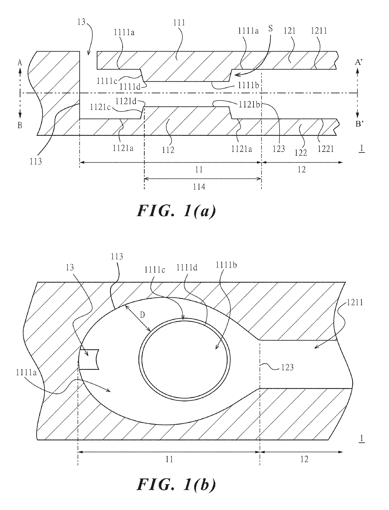
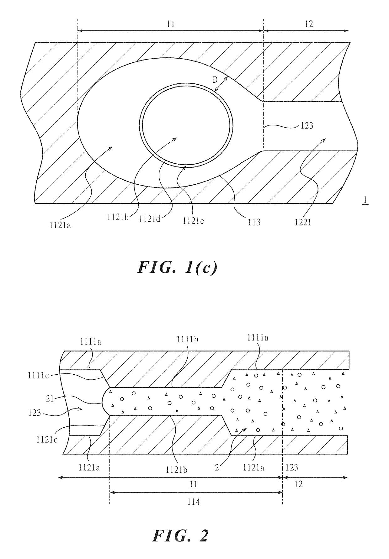
[0029]Please refer to FIGS. 1(a), 1(b) and 1(c), which are a vertical cross-section view of a first embodiment of a fluid inspection device in the present invention and cross-section views according to cutting lines A-A′ and B-B′ in FIG. 1(a) respectively. In the first embodiment of the present invention, the fluid inspection device 1 comprises a chamber 11, a channel 12 and a through hole 13, wherein the chamber 11 includes a top chamber portion 111, a bottom chamber portion 112 and a lateral wall 113, and the channel 12 includes a top channel portion 121, a bottom channel portion 122 and a channel end 123. The top chamber portion 111 joins the top channel portion 121, the bottom chamber portion 112 joins the bottom channel portion 122, and the chamber 11 interconnects the channel 12 through the channel end 123. The top chamber portion 111 includes a top chamber surface 1111 and the bottom chamber portion 112 includes a bottom chamber surface 1121, wherein the top chamber surface 1...


PUM

PropertyMeasurementUnit
areaaaaaaaaaaa
widthaaaaaaaaaa
internal diametersaaaaaaaaaa

Abstract

The present invention provides a fluid inspection device comprising at least one channel including a top channel surface and a bottom channel surface, and a first spacing formed therebetween; at least one chamber communicating with the at least one channel from which a fluid flows into the at least one chamber and including a top chamber surface, a bottom chamber surface and a fluid-filling area and a through opening communicating with the at least one chamber and the outside. A second spacing is formed between the top chamber surface of at least one portion of the fluid-filling area and a corresponding bottom chamber surface thereof, wherein the second spacing is smaller than the first spacing. The fluid inspection device prevents bubbles from producing in the chamber and obstructing the inspection and further allows less required fluid amount in the chamber.

Description

RELATED APPLICATIONS[0001]This application claims the priority of Chinese Patent Application No. 201610186901.3, filed on Mar. 29, 2016, at the State Intellectual Property Office of the P.R.C, the entire disclosure of which is incorporated herein by reference.FIELD OF THE INVENTION[0002]The present invention relates to an inspection device, specifically a fluid inspection device.BACKGROUND OF THE INVENTION[0003]Nowadays, the subject of a fluid inspection device with channels or micro-channels is quite popular. In the general course of fluid inspection, a tested fluid enters a chamber through a channel of the fluid inspection device for mixture or reaction in the chamber. During the tested fluid enters the chamber, it is easy for bubbles to come up in the chamber before the chamber is filled with the tested fluid and then the inspection is obstructed.[0004]Furthermore, since the internal diameters in the channel system or micro-channel system are tiny, the micro-pump or centrifugal f...

Claims


Application Information

Patent Timeline
Patent Type & Authority Patents(United States)
IPC IPC(8): B01L3/00G01N33/52
CPCG01N33/52G01N33/525B01L3/502723B01L3/50273B01L3/502B01L2300/0887B01L2300/0864B01L2400/0406B01L2200/0684B01L2300/0825B01L2300/089B01L2300/0848B01L2300/0851G01N21/05G01N2021/054
Inventor HO, SZU-HSIENWEI, CHIA-CHUNCHEN, HUNG-WEI
Owner SKYLA CORP HSINCHU SCI PARK BRANCH
Why Eureka
Try Eureka