X-ray tube device and x-ray CT apparatus
a tube device and computed tomography technology, applied in the direction of x-ray tube targets, electrical devices, x-ray tube targets and convertors, etc., can solve the problems of film peeling off and various problems such as discharg
- Summary
- Abstract
- Description
- Claims
- Application Information
AI Technical Summary
Benefits of technology
Problems solved by technology
Method used
Image
Examples
first embodiment
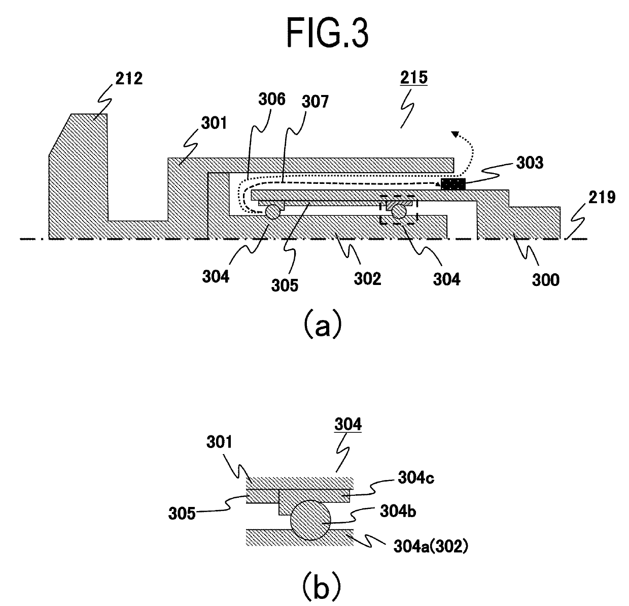
[0064]A first embodiment is described with reference to FIG. 3. In the embodiment, a magnet 303 as the attractor, which attracts the peeled-off solid lubrication films with the magnetic force, is disposed at a position in an opened end portion of the rotary cylinder 301 in the rotation axis 219 on the outer circumference of the cylinder portion of the fixed portion 300. The position of the opened end portion of the rotary cylinder 301 corresponds to an exit of the peeled-off solid lubrication films from the rotary-member support mechanism 215. The magnet 303 is disposed at the exit from the rotary-member support mechanism 215, and thereby the solid lubrication films scattering in a direction represented by a dotted arrow 306 are attracted to the magnet 303 in a direction represented by a dashed arrow 307. In order to attract the peeled-off solid lubrication films to the magnet 303, the ferromagnet such as iron needs to be mixed into the solid lubrication films. Therefore, the rotary...
second embodiment
[0069]A second embodiment is described with reference to FIG. 4. In the embodiment, a magnetic portion 400 is added to the configuration of the first embodiment and the magnetic portion 400 is used as the attractor. Hereinafter, the magnetic portion 400 will be described in detail.
[0070]In the rotary anode type X-ray tube device, in order to collect magnetic fields generated by the exciting coil 214, which are used as a rotational driving force of the rotary-member support mechanism 215, the cylindrical magnetic portion 400 is disposed on the outer circumference of the fixed portion 300 in some cases. A ferromagnet such as pure iron is used as the magnetic portion 400. The magnetic portion 400 is disposed on the outer circumference of the fixed portion, thereby the magnetic fields generated by the exciting coil 214 are collected to the magnetic portion 400, and it is possible to cause the rotary cylinder 301 to efficiently rotate.
[0071]In the embodiment, in order to use the magnetic...
third embodiment
[0074]A third embodiment is described with reference to FIG. 5. In the embodiment, a magnet 500 is added as the attractor to the configuration of the first embodiment. Hereinafter, the magnet 500 will be described in detail.
[0075]In the embodiment, the magnet 500 is provided on the bottom in the fixed portion 300. The magnet 500 is a disk-shaped permanent magnet and, for example, the same permanent magnet as used in the first embodiment is used. The position, at which the magnet 500 is disposed in FIG. 5, is a position apart from the anode 212 as a heating portion, has a relatively low temperature in the X-ray tube 210, and thus has a temperature lower than the Curie point of the permanent magnet used. In addition, the magnet 500 is not in direct contact with the rotary bearing 304, and the fixed portion 300 made of copper is disposed between both thereof.
[0076]The peeled-off solid lubrication films not only result in the discharge in the X-ray tube 210, but also the films are reatt...
PUM
 Abstract
Description
Claims
Application Information
 - R&D
- Intellectual Property
- Life Sciences
- Materials
- Tech Scout
- Unparalleled Data Quality
- Higher Quality Content
- 60% Fewer Hallucinations
Browse by: Latest US Patents, China's latest patents, Technical Efficacy Thesaurus, Application Domain, Technology Topic, Popular Technical Reports.
© 2025 PatSnap. All rights reserved.Legal|Privacy policy|Modern Slavery Act Transparency Statement|Sitemap|About US| Contact US: help@patsnap.com


