Low-flow emitter

a low-flow, emitter technology, applied in watering devices, horticulture, agriculture, etc., can solve the problem of difficult precise control of the position of the emitter sleeve, and achieve the effect of convenient manipulation, precise flow rate adjustment, and simple structur

Active Publication Date: 2019-11-05
ARIA PROD L L C
View PDF9 Cites 3 Cited by
  • Summary
  • Abstract
  • Description
  • Claims
  • Application Information

AI Technical Summary

Benefits of technology

[0007]It is therefore one or more aspects to a low-flow emitter with simple structure and convenient manipulation, and the low-flow emitter offers precise flow rate adjustment.

Problems solved by technology

However, the position of the emitter sleeve is difficult to control precisely.

Method used


Image

  • Low-flow emitter
  • Low-flow emitter
  • Low-flow emitter

Examples


first embodiment

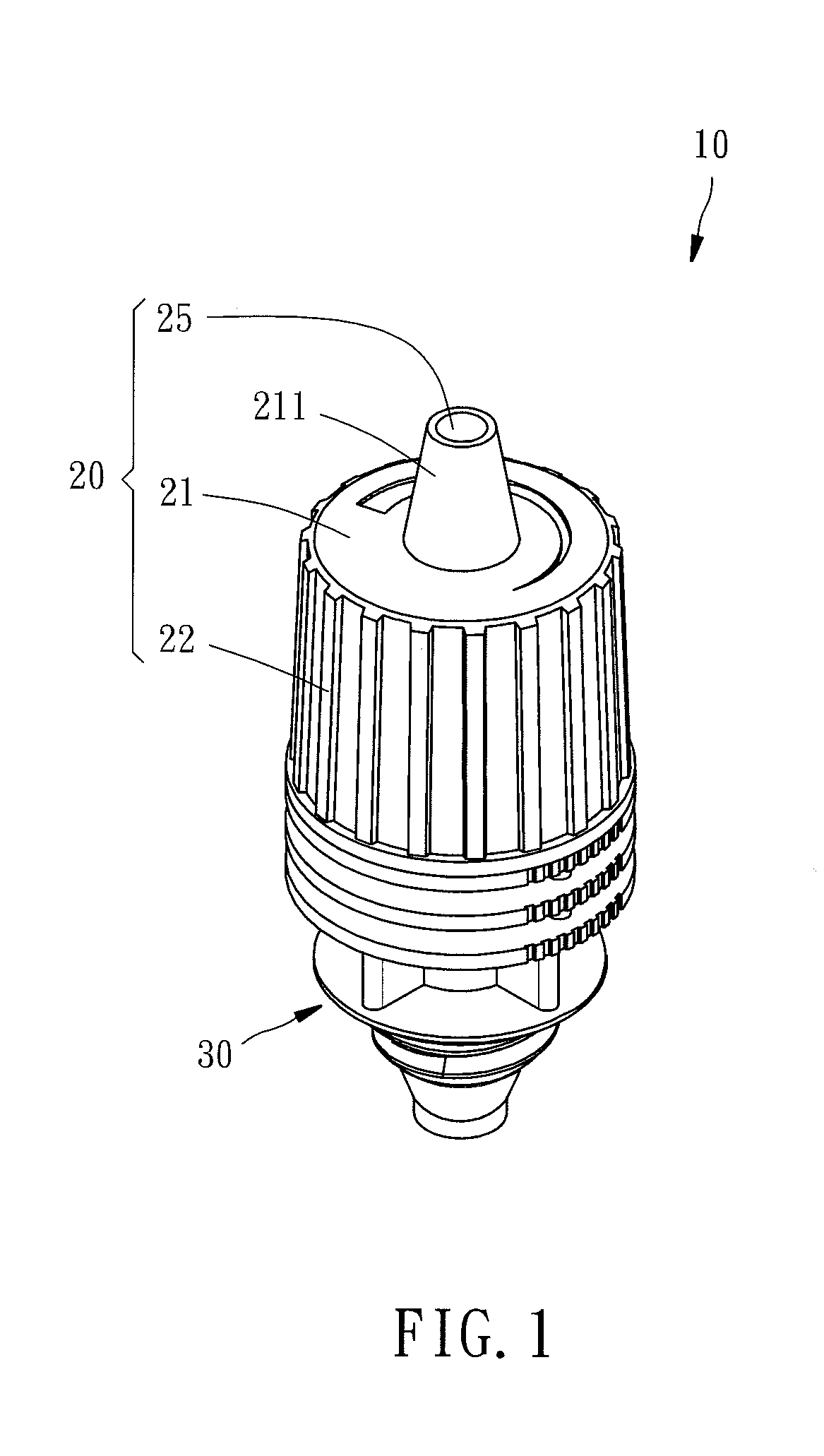
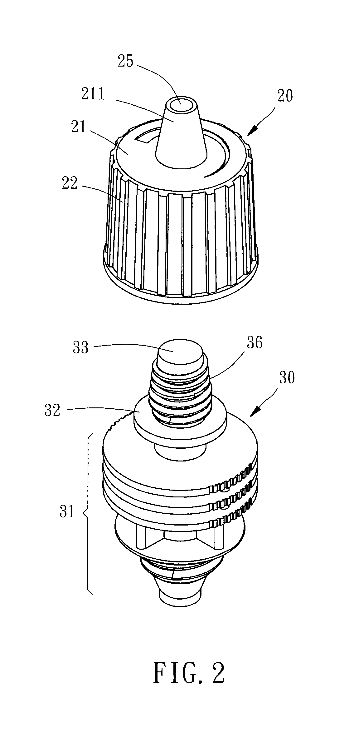
[0026]FIGS. 1 through 4 pertain to a first embodiment of the invention.

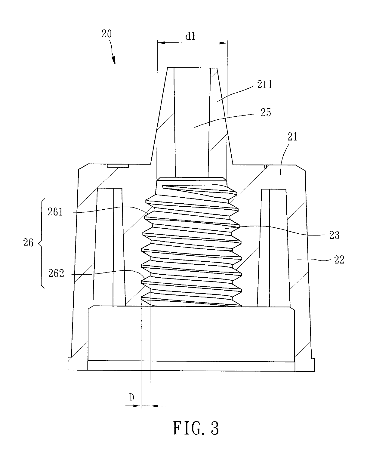
[0027]The first housing 20, referring to FIGS. 1 and 3, includes an end member 21, a circumference member 22, a tubular head 211, a first passage 25, an exterior thread bore 23, and a first thread portion 26. A top of the circumference member 22 borders a periphery of the end member 21. The tubular head 211 extends from an exterior face of the end member 21. The first passage 25 is coaxially formed in the tubular head 211. The exterior thread bore 23 is formed from an interior face of the end member 21, and coaxially corresponds with the tubular head 211. The first thread portion 26 is formed in the exterior thread bore 23.

[0028]The first thread portion 26 includes a first thread section 261 and a second thread section 262 connected with each other. The first thread section 261 defines a major diameter d1 which increases gradually in a direction away from the first passage 25. Therefore, the first thread section ...

second embodiment

[0037]FIG. 6 pertains to a low-flow emitter 10a according to a second embodiment of the invention, which is similar to the first embodiment in that the first housing 20a includes a first thread portion 26a having a first thread section 261a, the second housing 30a includes a second thread portion 36a having a third thread section 361a, and a spiral passage 12a is formed between the first and third thread sections 261a, 361a.

[0038]The low-flow emitter is specially adapted for hanging irrigation where water flows through a first passage 25a in a downward manner. It should be comprehended that the second and fourth thread sections are omitted in the case.

third embodiment

[0039]FIGS. 7 to 11 pertain to a third embodiment of the invention. A low-flow emitter 10b includes a first housing 20b, a second housing 30b, and a spiral passage 12b.

[0040]The first housing 20b, referring FIGS. 7 to 9, includes an end member 21b, a circumference member 22b, an abutting face 24b, four first passages 25b, an exterior thread bore 23b an interior thread axle 29b, and a first thread portion 26b. A top of the circumference member 22b borders a periphery of the end member 21b. The abutting face 24b is formed from an interior face of the end member 21b and adjacent to the circumference member 22b. The four first passages 25b are formed on the end member 21b. The exterior thread bore 23b extends from an interior face of the end member 21b. The interior thread axle 29b is coaxially arranged through the exterior thread bore 23b.

[0041]The first thread portion 26b includes a first thread section 261b and a second thread section 262b. The first thread section 261b is arranged...


PUM


Abstract

A low-flow emitter includes a first housing and a second housing. The first housing includes a first thread portion, and a first passage defined in the first thread portion. The second housing includes a second thread portion, and a second passage defined in the second thread portion corresponding with the first thread portion in a thread connection. Part of the thread connection between the first and second housings is a loose fitting thread connection. A spiral passage is formed along the loose fitting thread connection between the first and second housings. Water flow rate is able to be controlled by a rotation of the first housing with respect to the second housing.

Description

BACKGROUND OF THE INVENTION[0001]1. Field of the Invention[0002]The present invention relates to a drip emitter, specifically to a low-flow emitter which offers precise control of water flow rate.[0003]2. Description of the Related Art[0004]In low-flow irrigation, sometimes known as micro-irrigation, water is delivered to the irrigation area at low and uniform flow rate, thereby conserving water.[0005]For low-flow emitter, a typical method of flow rate adjustment is controlling the size of an opening through which water passes through to the emitter nozzle. For example, China Publication No “CN202238389” discloses a drip hole formed on a thread emitter core. An emitter sleeve shadowing the drip hole reduces the flow rate. The flow rate can be controlled by the relative overlapping between the emitter sleeve and the drip hole. However, the position of the emitter sleeve is difficult to control precisely.[0006]In the interest of water conservation, a low-flow emitter having precise ad...

Claims


Application Information

Patent Timeline
Patent Type & Authority Patents(United States)
IPC IPC(8): B05B1/30A01G25/02
CPCB05B1/3033A01G25/023
Inventor WANG, DANIEL CHUN
Owner ARIA PROD L L C
Why Eureka
Try Eureka