
Optimized flow compensator

a compensator and flow nozzle technology, applied in the direction of the muzzle attachment, etc., can solve the problems of less muzzle rise, bright flash and concussion felt by the shooter and those nearby, and more problems than they solve, so as to minimize back-blast and flash experience, the effect of high efficiency

Active Publication Date: 2019-11-05
WALKER DREW NOLLE
View PDF68 Cites 2 Cited by
  • Summary
  • Abstract
  • Description
  • Claims
  • Application Information

AI Technical Summary

Benefits of technology

The system effectively reduces both horizontal and vertical recoil, minimizes flash and back-blast, and enhances the counter-recoil force by redirecting gases for a more direct impact, improving the shooter's visibility and reducing the risk of detection.

Problems solved by technology

Muzzle brakes, categorically, are seen as being incompatible with combat, as they are often criticized as causing more problems than they solve.
Most gases exit this type of design laterally outward to the sides of the compensator and strike the cooler air of the outside atmosphere all at once, causing a bright flash and concussion felt by the shooter and those nearby.
The result is lessened muzzle rise but also a blinding flash appearing directly in the shooter's immediate field of view.

Method used


Image

  • Optimized flow compensator
  • Optimized flow compensator
  • Optimized flow compensator

Examples


Embodiment Construction

[0029]Unconventional compensator designs, such as those featuring an asymmetric expansion chamber with a prominent anti-recoil surface, may allow gases to expand and, in doing so, strike a baffle surface and impart some force, which combats the gun's recoil indirectly. In this design, gases do not strike the baffle surface head-on, or rather, normal to the baffle's surface. Instead, gases strike the baffle surface at a glancing angle—this is highly inefficient, as more energy is transferred when gases strike normal to a counter-recoil surface. Leveraging the principles and insight gathered from studying fluid dynamics as it relates to firearms, specifically compressible supersonic and even hypersonic flow, it becomes readily apparent that massive levels of force, friction, velocity, heat, etc. are present. Where the gas flows, force and energy follow as well. Even what may seem like a somewhat small change in flow can yield vastly different results given the forces at work. That sai...


PUM


Abstract

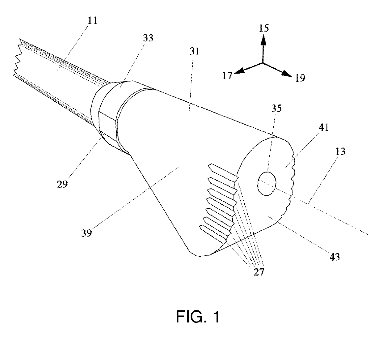
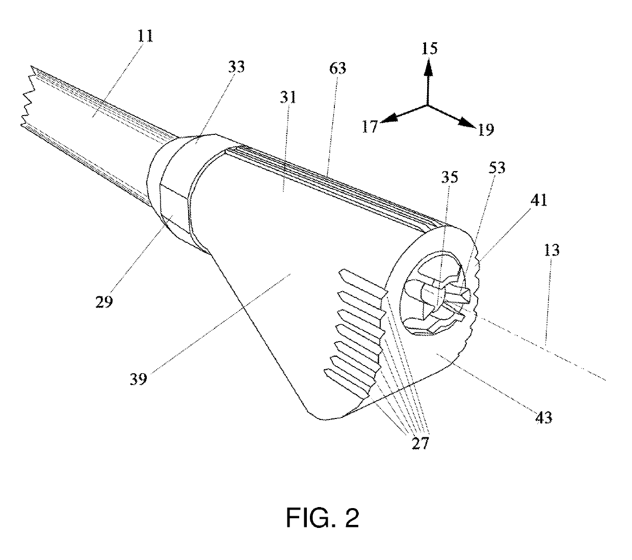
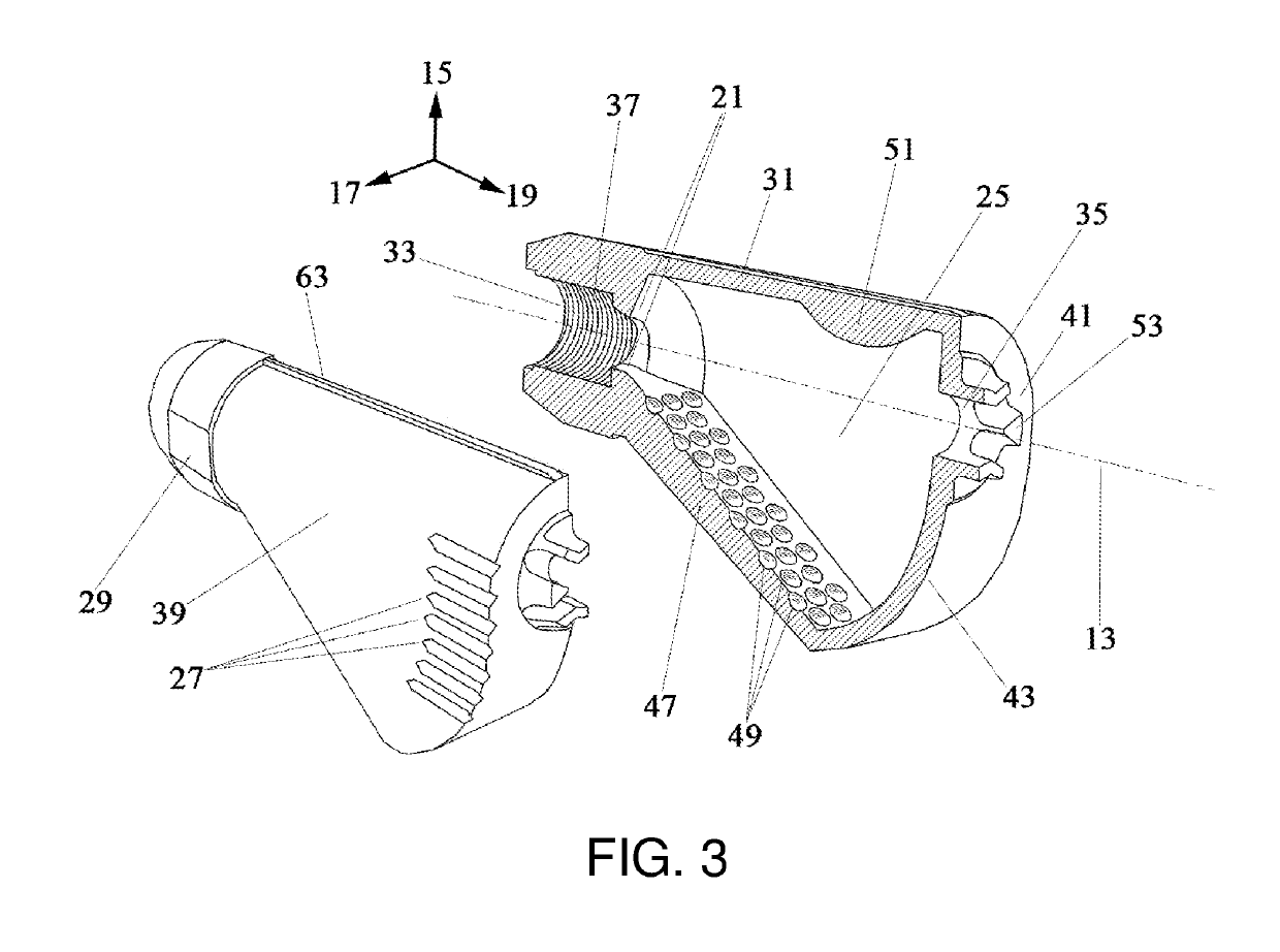
A firearm compensator, to be affixed to the muzzle of a gun for reducing at least one of flash and recoil, utilizes a vectored flow nozzle, an expansion chamber containing a prominent thrust surface and flow-directing structures below the barrels center line, and flash-hiding ports. A compression ramp containing dimple-like structures connects the bottom of the gun muzzle to the bottom of the prominent thrust surface. Upon firing the gun, gasses depart from their linear trajectory as they flow past the vectored flow nozzle, flow diagonally downward past a dimpled compression ramp in the expansion chamber, and strike the thrust surface. A plurality of substantially horizontal elongated ports in the expansion chamber aids in flash suppression.

Description

CROSS-REFERENCE TO RELATED APPLICATIONS[0001]This application claims the benefit of the filing date of U.S. Provisional Patent Application No. 62 / 203,552 filed Aug. 11, 2015, the disclosure of which is hereby incorporated herein by reference.FIELD OF INVENTION[0002]This invention relates to the field of recoil-reducing muzzle devices for firearms. More specifically, the invention comprises a vectored flow nozzle and expansion chamber with a means of substantially diverting the main, forward trajectory of gas flow of a gunshot to strike a surface more directly, thereby producing a counterforce to reduce recoil.BACKGROUND OF THE INVENTION[0003]Muzzle brakes, categorically, are seen as being incompatible with combat, as they are often criticized as causing more problems than they solve. To define terms, muzzle brakes are muzzle devices that are affixed to the end of a firearm's muzzle for the primary purpose of reducing recoil. The term “compensator” is often used synonymously. Regardl...

Claims


Application Information

Patent Timeline
Patent Type & Authority Patents(United States)
IPC IPC(8): F41A21/36
CPCF41A21/36
Inventor WALKER, DREW NOLLE
Owner WALKER DREW NOLLE
Learn More