Bleed flow duct for a turbomachine comprising a passively actuated variable cross section VBV grating

a technology of vbv grating and bleed flow duct, which is applied in the direction of machines/engines, engine components, jet propulsion plants, etc., can solve the problems of increasing the mass of the engine and the addition of components, and achieves the effect of simple and easy implementation, reducing surface irregularities, and increasing the mass of the turbine engin

Active Publication Date: 2019-11-19
SN DETUDE & DE CONSTR DE MOTEURS DAVIATION S N E C M A
View PDF10 Cites 5 Cited by
  • Summary
  • Abstract
  • Description
  • Claims
  • Application Information

AI Technical Summary

Benefits of technology

[0023]One objective of the invention is therefore to propose a bypass turbine engine comprising discharge valves allowing a reduction in the surface irregularities which can create head losses or separate the secondary flow in the secondary stream, which is simple and easy to implement, without increasing the mass of the turbine engine in the process.

Problems solved by technology

However, these blocking means require the implementation of servo control means and therefore the addition of components into the engine and therefore the increase of its mass.

Method used


Image

  • Bleed flow duct for a turbomachine comprising a passively actuated variable cross section VBV grating
  • Bleed flow duct for a turbomachine comprising a passively actuated variable cross section VBV grating

Examples


Embodiment Construction

[0043]Hereafter, an intermediate casing hub 2 for a bypass turbine engine and an associated intermediate casing with now be described with reference to the appended figures.

[0044]The intermediate casing hub parts 2 of the prior art already described are also present in the embodiments hereafter.

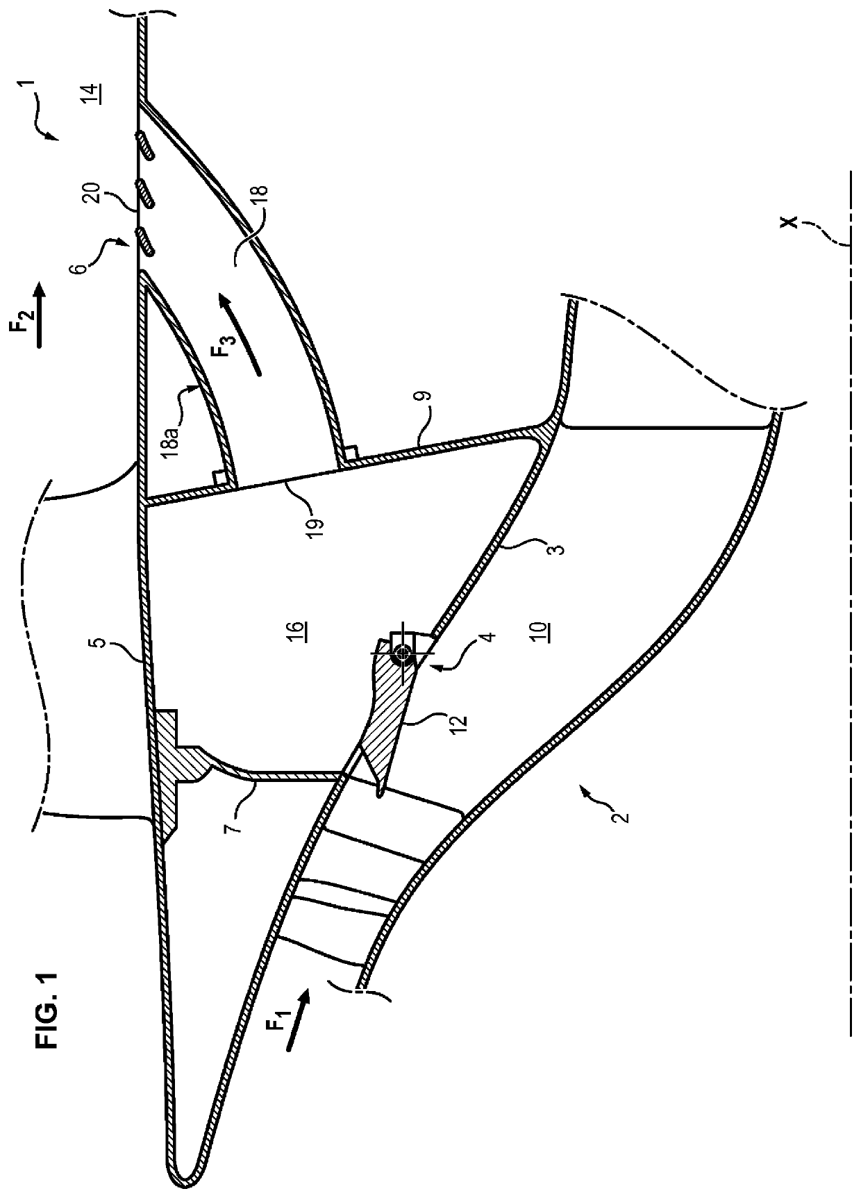
[0045]In particular, an intermediate casing hub 2 according to the invention comprises:[0046]an inner shroud 3 configured to delimit a primary flow space 10 of the primary gas flow of the turbine engine,[0047]an outer shroud 5 configured to delimit a secondary flow space 14 of the secondary gas flow of said turbine engine, and[0048]a discharge stream duct 18, extending between the inner shroud 3 and the outer shroud 5.

[0049]The discharge stream duct 18 leads into the primary flow space 10 through an inlet opening 4 formed in the inner shroud 3 and into the secondary flow space 14 through an outlet opening 6 formed in the outer shroud 5. As previously described, the hub 2 can further comprise ...


PUM


Abstract

The invention relates to a hub (2) of an intermediate casing (1) for a bypass turbomachine comprising: —a bleed stream duct (18), —a bleed valve, comprising a mobile door at the inlet orifice to the bleed stream duct (18), —a set of bleed vanes (22) which are mounted with the ability to rotate about a pivot (26) in the bleed stream duct (18) between an open configuration in which a flow of air coming from the inlet orifice (4) passes between the bleed vanes (22) and a closed configuration, the pivot (26) for each bleed vane (22) being closer to its leading edge (BA) than to its trailing edge (BF).

Description

FIELD OF THE INVENTION[0001]The invention relates to the general field of bypass turbine engines, and more particularly to discharge valves allowing the regulation of the air leaving a compressor of such a turbine engine, said valves sometimes being designated by their acronym VBV (variable discharge valves).TECHNOLOGICAL BACKGROUND[0002]A bypass turbine engine generally comprises, from upstream to downstream in the gas flow direction, a shrouded fan, an annular primary flow space and an annular secondary flow space. The air mass aspired by the fan is therefore divided into a primary flow F1, which circulates in the primary flow space, and a secondary flow F2, which is concentric with the primary flow F1 and circulates in the secondary flow space.[0003]The primary flow space passes through a primary body comprising one or more compressor stages, for example a lowpressure compressor and a highpressure compressor, a combustion chamber, one or more turbine stages, for example a highpre...

Claims


Application Information

Patent Timeline
Patent Type & Authority Patents(United States)
IPC IPC(8): F02K3/075F02C9/18F01D17/14
CPCF02K3/075F01D17/148F02C9/18F05D2220/323F05D2240/129F05D2300/522F01D17/105
Inventor BRUHAT, JEAN-FREDERIC PIERRE JOSEPH
Owner SN DETUDE & DE CONSTR DE MOTEURS DAVIATION S N E C M A
Why Eureka
Try Eureka