Display device

a display module and display technology, applied in the direction of casings/cabinets/drawers, instruments, casings/cabinets/drawers, etc., can solve the problems of affecting the efficiency of display devices, etc., to reduce the possibility of mixture, enhance heat radiation efficiency, and effectively emit heat generated in display modules

Active Publication Date: 2019-11-19
LG ELECTRONICS INC
View PDF25 Cites 21 Cited by
  • Summary
  • Abstract
  • Description
  • Claims
  • Application Information

AI Technical Summary

Benefits of technology

[0028]The display device according to at least one embodiment mentioned above is capable of enhancing heat radiation efficiency.
[0029]Furthermore, the display device according to at least one embodiment is capable of emitting the heat generated in the display module effectively.
[0030]Still further, the display device according to at least one of the embodiments is able to reduce the possibility of the mixture between inlet air and outlet air.
[0031]Still further, the display device according to at least one embodiment is able to making the direction of natural convection be equal to the direction of forcible convection.
[0032]Still further, the visibility of the inlet and the outlet of the open hole may be minimized.

Problems solved by technology

The display device is likely to be neglected under a high outdoor temperature.
However, external air is not directly heat exchanged with a heat generation region in the indirect cooling method and heat radiation efficiency may be a major issue in the indirect cooling method.
If only one circulation structure is provided, the internal air which has failed heat exchange might pass other heat generation regions as it is only to fail sufficient heat exchange.

Method used


Image

  • Display device
  • Display device
  • Display device

Examples


Embodiment Construction

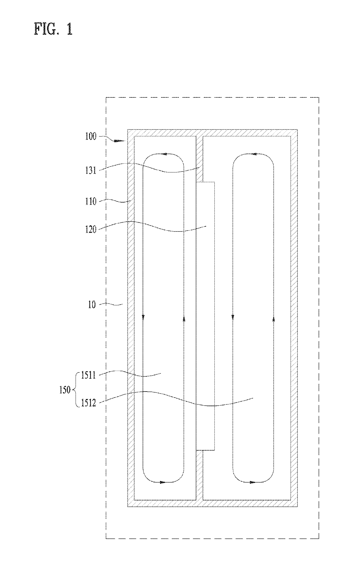
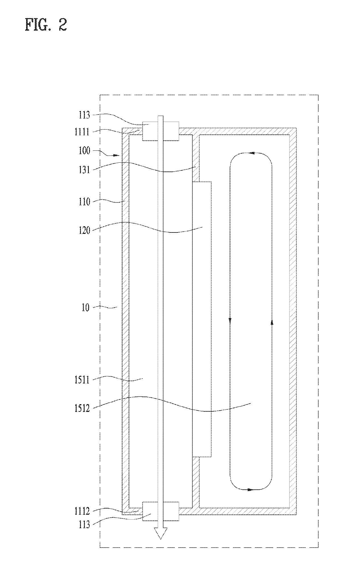
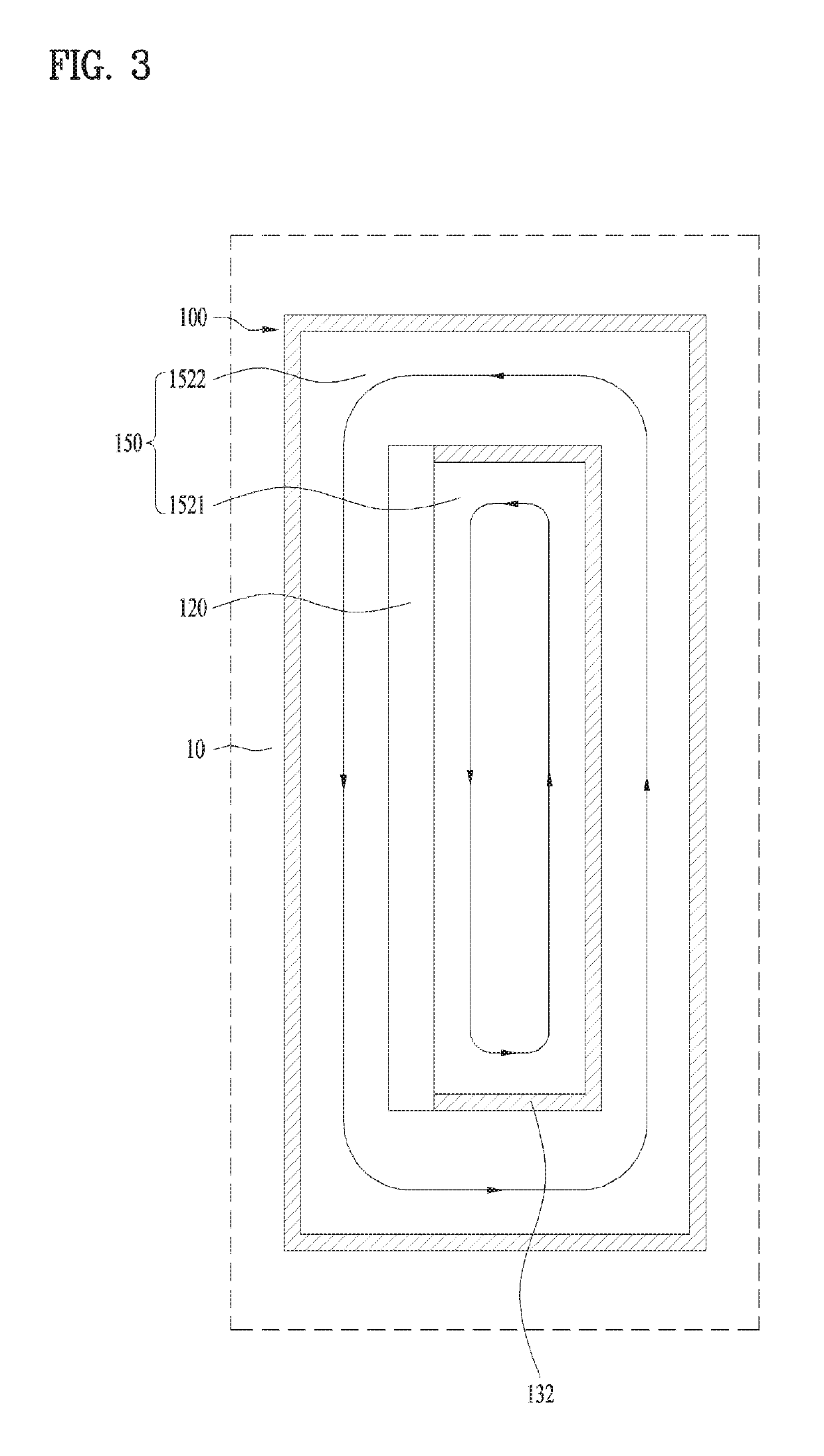
[0048]Description will now be given in detail according to exemplary embodiments disclosed herein, with reference to the accompanying drawings. For the sake of brief description with reference to the drawings, the same or equivalent components may be provided with the same reference numbers, and description thereof will not be repeated. In general, a suffix such as “module” and “unit” may be used to refer to elements or components. Use of such a suffix herein is merely intended to facilitate description of the specification, and the suffix itself is not intended to give any special meaning or function. In the present disclosure, that which is well-known to one of ordinary skill in the relevant art has generally been omitted for the sake of brevity. The accompanying drawings are used to help easily understand various technical features and it should be understood that the embodiments presented herein are not limited by the accompanying drawings. As such, the present disclosure should...


PUM


Abstract

There is disclosed a display device comprising a display module, an outer case in which the display module is mounted and defining an internal space which is closed airtight from the outside, and an inner case coupled to the display module, wherein the inner case which partitions off the internal space into a first closed space having a rear surface of the display module exposed thereto and a second closed space having a front surface of the display module exposed thereto, and the first closed space is surrounded by the second closed space with respect to one cross section.

Description

CROSS-REFERENCE TO RELATED APPLICATIONS[0001]Pursuant to 35 U.S.C. § 119(a), this application claims the benefit of earlier filing date and right of priority to Korean Patent Application No. 10-2017-0030164, filed on Mar. 9, 2017, the contents of which are hereby incorporated by reference herein in its entirety.BACKGROUND OF THE DISCLOSURE[0002]Field of the Disclosure[0003]Embodiments of the present disclosure relate to a display device which considers a heat radiation structure.[0004]Background of the Disclosure[0005]A display device means one mechanical unit which defines a display module mounted therein.[0006]Such a display device usually has a large-inch display and is located in an external surface of which the temperature is very different from ambient temperatures and which has many foreign substances such as dust.[0007]Under such environmental conditions, the display device has a relatively high brightness to secure a sufficient outdoor visibility. The display device is like...

Claims


Application Information

Patent Timeline
Patent Type & Authority Patents(United States)
IPC IPC(8): H05K7/20H05K5/02H05K5/06G06F1/20
CPCH05K5/0217H05K5/069H05K5/0213H05K7/20972G06F1/20H05K7/20963H05K7/20954G06F1/1601G02F2201/36
Inventor OH, HONGLYEOLKIM, JINWOOKCHANG, HYEUKKIM, JOONGNYON
Owner LG ELECTRONICS INC
Why Eureka
Try Eureka