Vehicle frame member

a vehicle frame and member technology, applied in the field of vehicle frame members, can solve the problems of decreasing the mass efficiency of the vehicle frame member (maximum bending load/mass), and achieve the effects of reducing or preventing bending deformation, improving maximum bending load, and improving mass efficiency (maximum bending load/mass)

Active Publication Date: 2019-11-26
TOYOTA JIDOSHA KK
View PDF14 Cites 0 Cited by
  • Summary
  • Abstract
  • Description
  • Claims
  • Application Information

AI Technical Summary

Benefits of technology

[0040]Explanation follows regarding operation and advantageous effects of the vehicle frame member 20 of the present exemplary embodiment.
[0041]In the vehicle frame member 20, both opening-ends 24D of the inner panel 24 and both opening-ends 22D of the outer panel 22 respectively abut together and are joined. Thus, in contrast to a structure in which, for example, a flange formed at an outer panel and a flange formed at an inner panel are joined by spot welding, there is no portion that is used for joining and that does not contribute to improving maximum bending load, thereby improving mass efficiency (maximum bending load / mass) of the vehicle frame member 20.
[0042]Further, in the vehicle frame member 20, the beads 26 are formed at both of the abutting-joint portions W between the outer panel 22 and the inner panel 24. Thus, compared to a structure, for example, in which the beads 26 are not formed at the abutting-joint portions W between an outer panel and an inner panel, the section modulus is higher, enabling bending rigidity of the vehicle frame member 20 to be secured. Thus, the vehicle frame member 20 is capable of reducing or preventing bending deformation of the vehicle frame member 20 with respect to input (collision load) from the vehicle outer side toward the inner side, and, in particular, out-of-plane bending deformation of side-faces 20A of the vehicle frame member 20. Note that each side-face 20A of the vehicle frame member 20 is a portion including a side-plate portion 22B of the outer panel 22 and a side-plate portion 24B of the inner panel 24.
[0043]In the vehicle frame member 20, the opening-end 22D of the outer panel 22 and the opening-end 24D of the inner panel 24 are each positioned at the apex 26A of the bead 26. Namely, in the bead 26 divided with a boundary at the apex 26A, the bead-half 26B is formed at an opening-end 22D side of the outer panel 22, and the bead-half 26C is formed at an opening-end 24D side of the inner panel 24. Thus, in the vehicle frame member 20, neither the shape of the bead-half 26B nor the shape of the bead-half 26C is formed with an undercut, enabling the outer panel 22 and the inner panel 24 to be pressed more easily than, for example, in a structure in which the bead 26 is divided at an either side of a wall or a base of the bead 26. Further, it is possible to press the bead-half 26B of the outer panel 22 and the bead-half 26C of the inner panel 24 using a common mold.
[0044]Moreover, in the vehicle frame member 20, the apexes 26A of the beads 26 are positioned at the vehicle interior-exterior direction central position of the closed cross-section structure configured by the outer panel 22 and the inner panel 24, thereby improving the bending rigidity (maximum bending load) of the vehicle frame member 20 with respect to input (for example, collision load) from the vehicle outer side toward the inner side compared to a structure, for example, in which the apexes 26A of the beads 26 are positioned at a vehicle inner side of the central position. Namely, in the vehicle frame member 20, the rigidity at a vehicle interior-exterior direction central portion is improved by the beads 26, enabling out-of-plane deformation of the each side-face 20A with respect to input from the vehicle outer side toward the inner side to be reduced or prevented. Note that the “maximum bending load” here refers to the maximum bending load (bending load limit) which causes the vehicle frame member 20 to undergo plastic deformation.Second Exemplary Embodiment
[0045]Explanation follows regarding a vehicle frame member according to a second exemplary embodiment of the present invention.

Problems solved by technology

Thus, it becomes necessary for the flanges to be a predetermined size, decreasing the mass efficiency of the vehicle frame member (maximum bending load / mass).
Thus, in contrast to a structure in which, for example, a flange formed at an outer panel and a flange formed at an inner panel are joined by spot welding, there is no portion in the vehicle frame member that is used for joining and that does not contribute to improving maximum bending load, thereby improving mass efficiency of the vehicle frame member.

Method used


Image

  • Vehicle frame member
  • Vehicle frame member
  • Vehicle frame member

Examples


first exemplary embodiment

[0026]Explanation follows regarding a vehicle frame member according to a first exemplary embodiment of the present disclosure.

[0027]Vehicle Frame Member

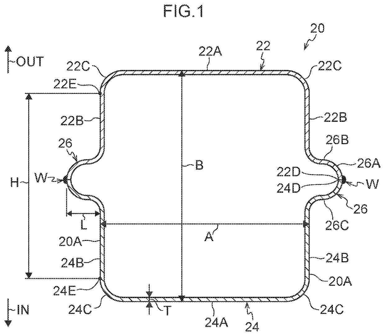
[0028]As illustrated in FIG. 1, a vehicle frame member 20 of the present exemplary embodiment is an elongated member made of metal, and is a member that configures a frame of a vehicle. The vehicle frame member 20 may be employed, for example, in a center pillar (B pillar), a dashboard cross member, front bumper reinforcement, a rear cross member, or rear bumper reinforcement. Note that the vehicle frame member 20 may be employed as a member other than the aforementioned vehicle frame configuration members.

[0029]The vehicle frame member 20 includes an outer panel 22, an inner panel 24, and beads 26. In FIG. 1, the arrow OUT indicates a vehicle outer side (collision load input side) and the arrow IN indicates a vehicle inner side, from the perspective of the vehicle frame member 20 when provided at a vehicle. Note that in cases in wh...

second exemplary embodiment

[0045]Explanation follows regarding a vehicle frame member according to a second exemplary embodiment of the present invention.

[0046]Vehicle Frame Member

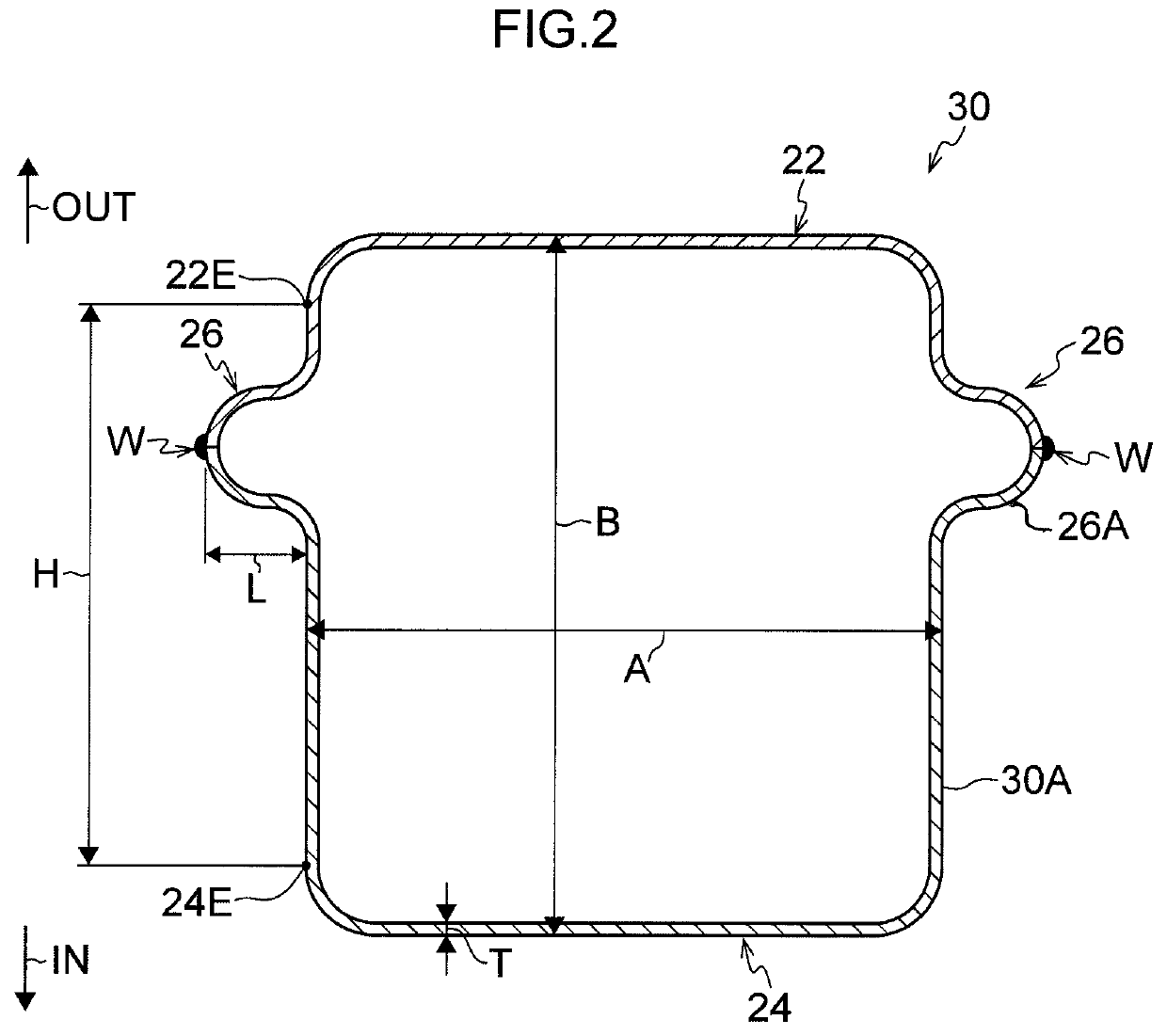
[0047]As illustrated in FIG. 2, a vehicle frame member 30 of the second exemplary embodiment is configured similarly to the vehicle frame member 20 of the first exemplary embodiment except with regard to the position of the beads 26, and so explanation follows regarding the position of the beads 26. Note that in the vehicle frame member 30, configurations similar to those of the vehicle frame member 20 of the first exemplary embodiment are appended with the same reference signs, and explanation thereof is omitted.

[0048]In the vehicle frame member 30, the apexes 26A of the beads 26 are positioned to a vehicle outer side of the vehicle interior-exterior direction central position of the closed cross-section structure configured by the outer panel 22 and the inner panel 24.

[0049]Explanation follows regarding operation and advantageous ...

example 1

[0059]The vehicle frame member of Example 1 has the same structure as the vehicle frame member 20 of the first exemplary embodiment (see FIG. 1). Accordingly, explanation of the vehicle frame member of Example 1 draws on the example of the vehicle frame member 20 of the first exemplary embodiment. The vehicle frame member of Example 1 is configured with cross-section size A (widthwise in the drawing)×B (heightwise in the drawing) of 65 mm×70 mm, and is configured with a plate thickness T of 1.0 mm. Further, the vehicle frame member of Example 1 is configured by a double layer of 1180 MPa grade sheet steel. Moreover, the apexes 26A (peak points) of the beads 26 are positioned at the vehicle interior-exterior direction central position. In other words, when the length of each side-face 20A of the vehicle frame member 20 is H, the apex 26A of each bead 26 is positioned at a position 0.5 H. Further, a projection height L of each bead 26 is 10 mm. Note that the length H of each side-face...


PUM


Abstract

A vehicle frame member includes: an outer panel configured to be disposed at a vehicle outer side, and having a U-shaped cross-section open toward a vehicle inner side; an inner panel configured to be disposed at the vehicle inner side, having a U-shaped cross-section open toward the vehicle outer side, and configuring a closed cross section structure together with the outer panel by both opening-ends of the inner panel respectively abutting and being joined to both opening-ends of the outer panel; and a bead formed at one or both abutting-joint portions between the outer panel and the inner panel, and projecting toward an outside of the closed cross section structure.

Description

CROSS-REFERENCE TO RELATED APPLICATION[0001]This application claims priority under 35 USC 119 from Japanese Patent Application No. 2017-056535 filed Mar. 22, 2017, the disclosure of which is incorporated by reference herein in its entirety.BACKGROUNDTechnical Field[0002]Preferred embodiments relate to a vehicle frame member.Related Art[0003]As a vehicle frame member having a closed cross-section structure, a vehicle frame member is known in which flanges of two panels, each configured with a hat-shaped cross-section, are spot welded together (for example, Japanese Patent Application Laid-Open (JP-A) No. 2015-089721).[0004]In the vehicle frame member in which the flanges of the two panels, each configured with a hat-shaped cross-section, are spot welded together, the flanges improve bending rigidity, and suppress out-of-plane deformation of side faces in the event of a collision.[0005]However, an extra area is necessary in the vicinity of a position for the spot welds in order to spo...

Claims


Application Information

Patent Timeline
Patent Type & Authority Patents(United States)
IPC IPC(8): B62D21/15B62D27/02
CPCB62D27/023B62D21/15B60R19/023B62D25/04B62D25/145B62D21/00B62D25/00
Inventor IKEDA, KOKIKANAGAI, SHUNSUKESAWA, YASUNORI
Owner TOYOTA JIDOSHA KK
Why Eureka
Try Eureka