
Rotational gravitational torque-generating system and method

a technology of rotational gravitational torque and torque generation system, which is applied in the direction of machines/engines, mechanical equipment, motors, etc., can solve the problems of unsuitable remote areas, unsuitable for remote areas, and dominating and obscure the landscape and its vistas

Active Publication Date: 2019-12-03
JENKINS ROBERT E
View PDF9 Cites 6 Cited by
  • Summary
  • Abstract
  • Description
  • Claims
  • Application Information

AI Technical Summary

Benefits of technology

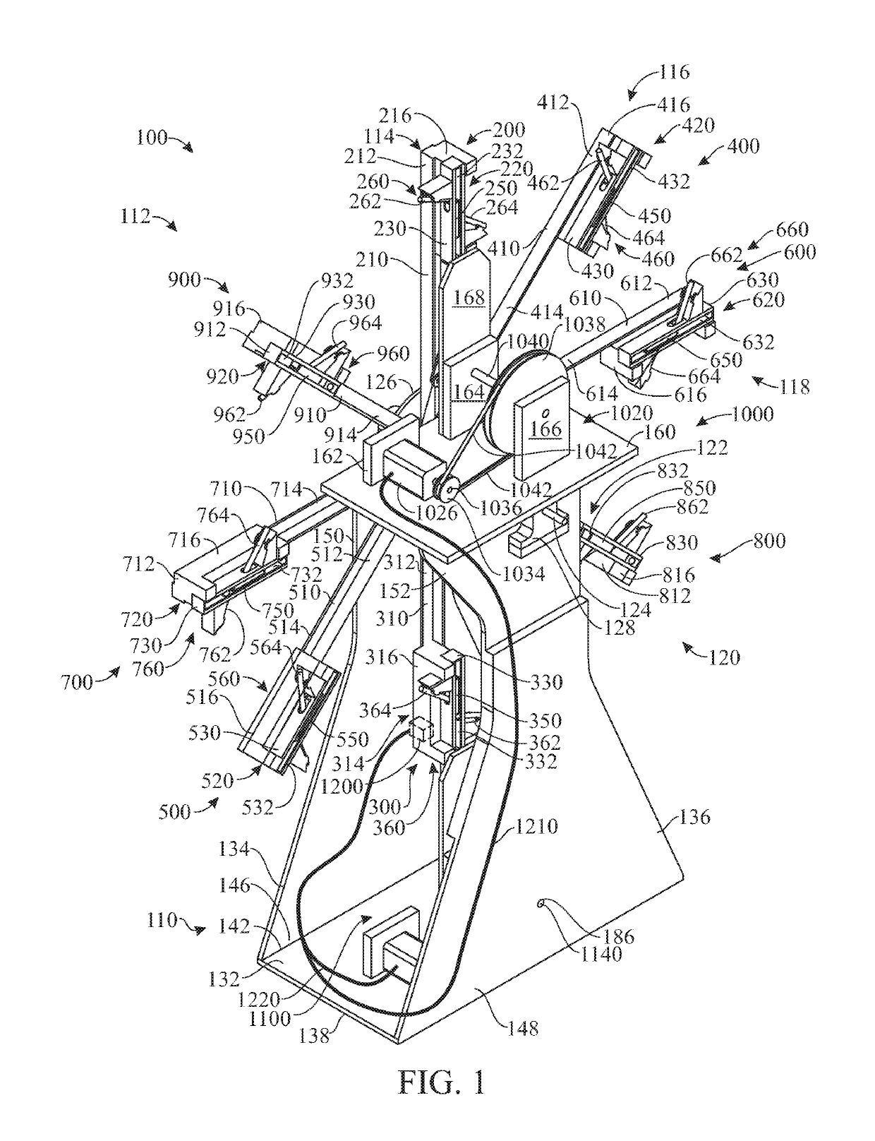
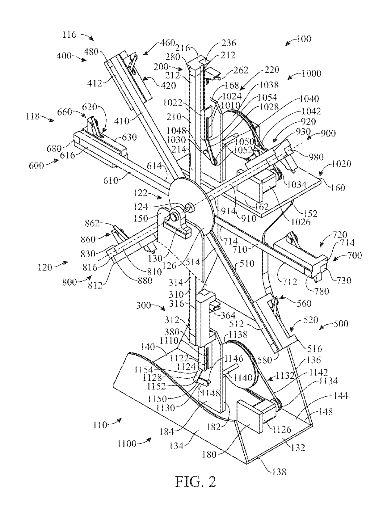
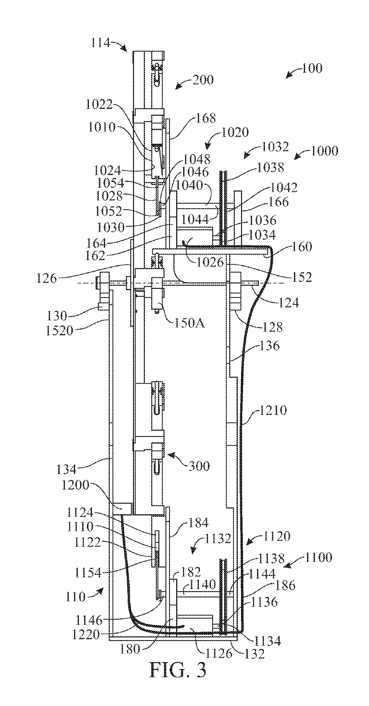
The present invention is a rotational gravitational machine that produces an output torque to power an external electrical generator or other rotational power consuming device. The machine includes a rotatable structure and a plurality of movable weight assemblies carried by the rotatable structure. Each movable weight assembly is designed to rotate about a radial axis and is angled in relation to the rotation axis. The machine also includes a magnetic biasing system to produce a torque arm that promotes rotation of the assembly about the rotation axis. The magnetic biasing system includes a movable magnetic weight and a magnetic piston that moves the magnetic weight between a radially innermost position and a radially outermost position. The machine can be controlled using a first or second magnetic piston, depending on the desired output torque. The machine can also include a central hub assembly and a plurality of arm assemblies carrying the movable weight assemblies. The movable weight assemblies can be rotatable through a top dead center position. The technical effects of the invention include an improved output torque, reduced weight and space requirements, and improved control of the magnetic biasing system.

Problems solved by technology

Nuclear power plants are very large scale operations that produce toxic materials, are very costly to construct, operate and maintain and are generally unsuitable for remote areas.
Coal fired power plants may be smaller but also are a source of toxic materials and produce by products such as mercury.
Wind turbines are controversial in that they require a large number of individual machines to be practical and they dominate and obscure the landscape and its vistas.
In addition, they obviously only work best in areas of a steady and sufficient wind flow and are unreliable at best in areas of varying wind conditions.
Finally, solar panels suffer similar limitations as they are unsightly when used on a large scale and require a steady and strong solar presence to produce power.
Obviously, they only operate during daylight hours limiting their usefulness to developing countries.

Method used


Image

  • Rotational gravitational torque-generating system and method
  • Rotational gravitational torque-generating system and method
  • Rotational gravitational torque-generating system and method

Examples


Embodiment Construction

[0051]The following detailed description is merely exemplary in nature and is not intended to limit the described embodiments or the application and uses of the described embodiments. As used herein, the word “exemplary” or “illustrative” means “serving as an example, instance, or illustration.” Any implementation described herein as “exemplary” or “illustrative” is not necessarily to be construed as preferred or advantageous over other implementations. All of the implementations described below are exemplary implementations provided to enable persons skilled in the art to make or use the embodiments of the disclosure and are not intended to limit the scope of the disclosure, which is defined by the claims. For purposes of description herein, the terms “upper”, “lower”, “left”, “rear”, “right”, “front”, “vertical”, “horizontal”, and derivatives thereof shall relate to the invention as oriented in FIG. 1. Furthermore, there is no intention to be bound by any expressed or implied theo...


PUM


Abstract

A rotational gravitational machine including a rotatable structure and a set of movable weight assemblies carried by the rotatable structure and jointly rotatable with the rotatable structure about a rotation axis. The movable weight assemblies are arranged radially spaced apart from the rotation axis and angularly spaced apart from each other. Each movable weight assembly includes a movable magnetic weight that can reciprocally and radially move between radially innermost and outermost positions relative to the rotation axis. A first magnetic biasing system is provided, including a radially movable, first magnetic piston which magnetically biases the movable magnetic weight between the radially innermost position and the radially outermost position in order to unbalance the assembly formed by the rotatable structure and movable weight assemblies. This unbalancing allows gravity to produce a torque arm that promotes rotation of the assembly about the rotation axis.

Description

CROSS-REFERENCE TO RELATED APPLICATION[0001]This application is a Continuation-in-Part of U.S. patent application Ser. No. 15 / 973,007, filed on May 7, 2018, which is a Continuation of U.S. patent application Ser. No. 14 / 843,641, filed on Sep. 2, 2015, which in turn claims the benefit of U.S. Provisional Patent Application Ser. No. 62 / 089,701, filed on Dec. 9, 2014, all of which are incorporated herein in their entirety.FIELD OF THE INVENTION[0002]The present invention relates generally to rotational gravitational machines and methods and, more particularly, to a rotational gravitational machine and method featuring a rotatable structure provided with radially moving pairs of magnetic weights, wherein rotation of the rotatable structure can cause the turning of a shaft, whose rotation can be used for producing electrical energy.BACKGROUND OF THE INVENTION[0003]It is important in today's society to provide a clean and safe source of energy in the form of electrical power. Additionally...

Claims


Application Information

Patent Timeline
IPC IPC(8): F03G3/00
CPCF03G3/00
Inventor JENKINS, ROBERT E.
Owner JENKINS ROBERT E
Learn More