
Time-lapse infrared thermography system and method for damage detection in large-scale objects

a time-lapse infrared thermography and large-scale object technology, applied in the direction of optical radiation measurement, image enhancement, instruments, etc., can solve the problems of insufficient heat for a large object, inability to adequately provide for large objects, and conventional infrared thermography may also require disruption to the operation of an object, so as to accurately measure internal defects of objects, improve maintenance efficiency, and improve the effect of efficiency

Active Publication Date: 2019-12-03
FUCHS CONSULTING
View PDF9 Cites 0 Cited by
  • Summary
  • Abstract
  • Description
  • Claims
  • Application Information

AI Technical Summary

Benefits of technology

[0009]The invention is directed to a system and method which more accurately measures internal defects in objects, in particular large-scale objects, i.e., objects of substantial size, for example concrete structures (e.g., bridges, buildings, dams, and nuclear containment vessels), military vessels (e.g., naval vessels), and the like, wherein the system and method are useful with the object in its place of use or operation, including during use or operation thereof. Application of the system and method of the invention provides an object or structure owner (the term “object” and “structure” being used interchangeably herein) with a more accurate picture of the internal condition of a structure so that maintenance can be more optimally coordinated.
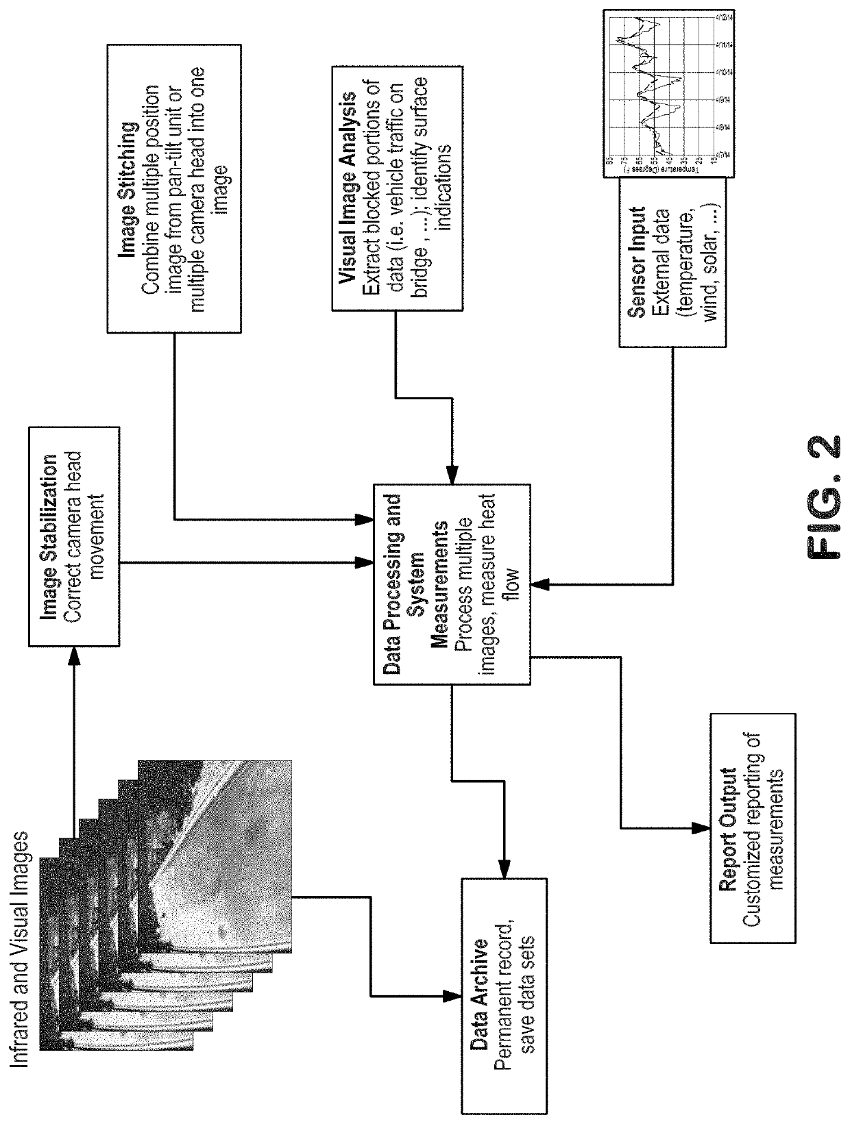
[0013]The system and method of the invention also can provide depth measurements of defects using infrared thermography on the objects analyzed. With the invention, multiple images are collected at different points in time, and data processing performed to not only by measurement detect the presence of a defect, but also measure the depth of the defect. Further, data processing can measure the rate of change of the heat flow through the object, which can better determine the depth of the defect.
[0015]The system and method of the invention can provide greater and more reliable documentation for objects or structures as compared to conventional measurements. The system and method produce a complete digital record that fully documents the spatial location of defects in an object or structure. The system and method can measure very large areas of an object or structure in one image or images.

Problems solved by technology

Active thermography with a user supplied heat source is very difficult or impossible to provide for objects of substantial size.
It is not possible to adequately provide sufficient heat for a large object, such as a concrete bridge deck, an entire building, or the flight deck of an aircraft carrier.
Conventional infrared thermography may also require disruption to the operation of an object, e.g., closing of a bridge deck to traffic in order to take measurements.

Method used


Image

  • Time-lapse infrared thermography system and method for damage detection in large-scale objects
  • Time-lapse infrared thermography system and method for damage detection in large-scale objects
  • Time-lapse infrared thermography system and method for damage detection in large-scale objects

Examples


Embodiment Construction

[0030]The infrared and visual measurement and data processing system of the invention is, in particular, useful for measuring objects or structures of large scale, i.e., of substantial size, to determine the location of internal defects in the objects and includes the taking of multiple infrared images and multiple visual images over an extended period of time in order to improve the detection and measurements of defects and overcome the limitations of conventional infrared thermography.

[0031]Hardware Components

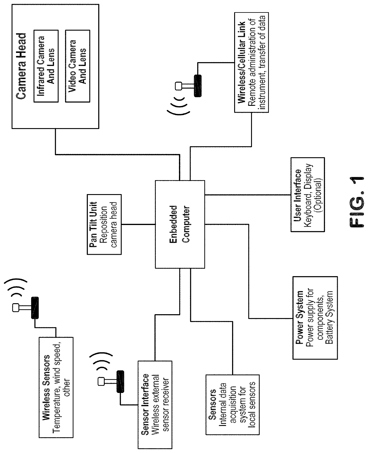
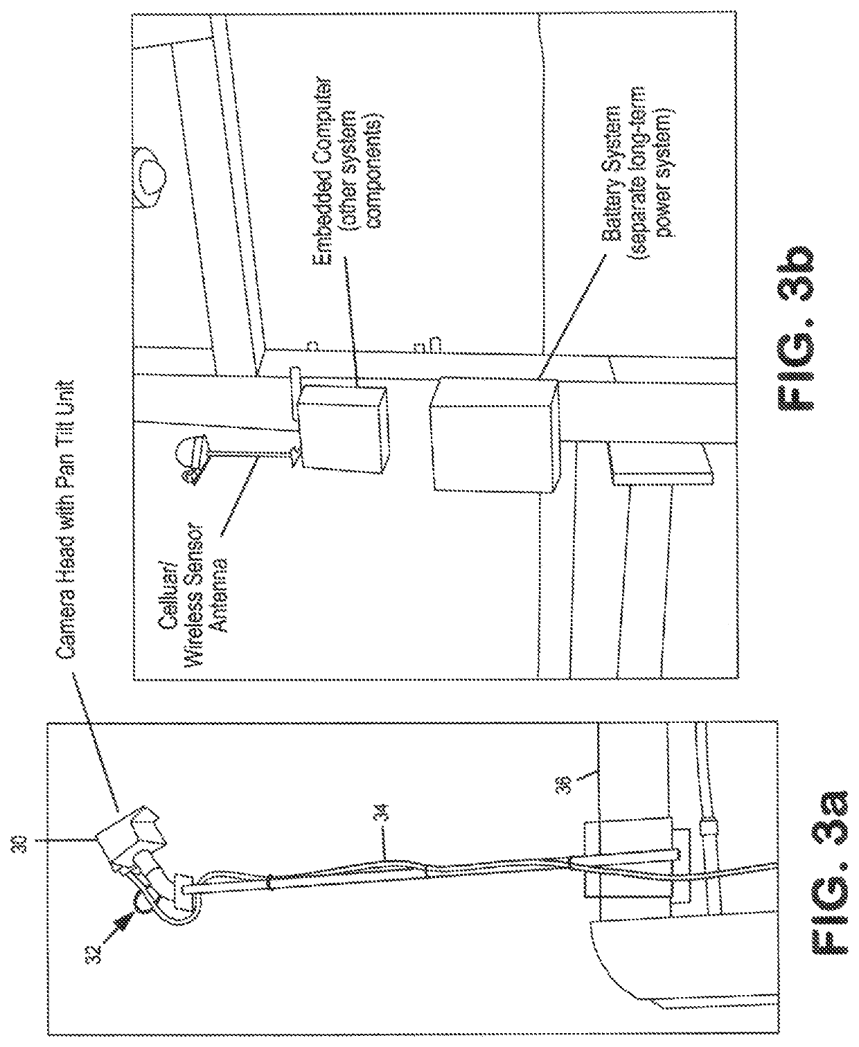
[0032]Described below are hardware components of presently preferred embodiments of the invention. The primary hardware components of a preferred embodiment are shown in FIGS. 1, 3a-3b and 4a-4f, and are described in detail below. However, it is understood that other hardware components and configurations may be used without departing from the scope of the invention.

[0033]Infrared Camera and Lens

[0034]An infrared (IR) camera is used to measure radiant flux or temperature of a...


PUM

PropertyMeasurementUnit
timeaaaaaaaaaa
heightaaaaaaaaaa
data over timeaaaaaaaaaa

Abstract

An infrared measurement system and method including taking multiple time lapse infrared images and visual images of a large-scale object over an extended period of time and analyzing such in order to better measure internal defects are described. Data collected over extended intervals of time are processed to provide measurements which are not affected by ambient conditions and the material properties of the object. The system may include infrared camera(s), visual (video) camera(s), external sensor(s), and an embedded computer.

Description

RELATED APPLICATIONS[0001]The present application claims benefit of U.S. Provisional Application Ser. No. 62 / 238,485 filed Oct. 7, 2015, which is incorporated herein by reference.FIELD OF INVENTION[0002]The invention is directed to a system and method involving a measurement and data processing system that may be positioned on or near an object, which is substantial in size, for an extended period of time and that takes time-lapse measurements of the object in order to detect internal defects in the object. The system uses infrared thermography to monitor how heat flows through objects over an extended period of time and also monitors the surrounding environmental conditions of the object. The system includes an infrared camera, a visual camera, an embedded computer and associated components, and an environmental data collection source, preferably external sensors. The system is left in-place for a period of time imaging one or more predetermined areas of the object periodically ove...

Claims


Application Information

Patent Timeline
Patent Type & Authority Patents(United States)
IPC IPC(8): H04N7/18H04N5/247G06T7/00H04N5/33G06K9/00G01N25/72H04N5/225H04N5/232G01J5/00
CPCG06K9/00771H04N5/247H04N5/33G06T7/001H04N5/232H04N5/2252G01N25/72H04N5/23206G06T2207/10048G06T2207/30132G06T2207/10016G06T2207/30184G01J2005/0081G01J5/48G06V20/52H04N23/51H04N23/661H04N23/695H04N23/90
Inventor FUCHS, PAUL A.
Owner FUCHS CONSULTING
Learn More