
Oil injection apparatus

a technology of oil injection apparatus and oil pump, which is applied in the direction of lubricating pumps, shafts and bearings, lubricating elements, etc., can solve the problems of low grease discharge pressure, bearing damage, and insufficient detection of grease shortage, so as to prevent stagnation of lubricating oil, prevent the back pressure of lubricating oil, and ensure the effect of pumping operation

Active Publication Date: 2019-12-10
KLT CO LTD
View PDF16 Cites 1 Cited by
  • Summary
  • Abstract
  • Description
  • Claims
  • Application Information

AI Technical Summary

Benefits of technology

The apparatus achieves stable lubricating oil supply with reduced manufacturing costs and space requirements, preventing stagnation and oil separation, and ensuring efficient lubrication to multiple locations using a compact and simple design.

Problems solved by technology

Although the use of the oil injection apparatus is increasing, many problems associated with the use of the oil injection apparatus occur in industrial sites for reasons described below.
In this case, since the grease may be misperceived to remain in the container, grease shortage is not properly detected.
This is likely to lead to bearing damage.
The screw down system is advantageous over the positive displacement pump system in terms of the bleed rate, but has a limitation in that it has a low grease discharge pressure.
This oil injection apparatus has a complicated structure and is high in manufacturing cost and energy consumption.
Further, since it is necessary to lift the wedge slide with the force of a spring, when flowability of grease is poor due to low temperature or high viscosity of the grease, resistance increases, leading to fluctuation in the amount of grease discharged.
When the oil separation occurs, flowability of grease is deteriorated, and thus the grease cannot be efficiently introduced into the pump.

Method used


Image

  • Oil injection apparatus
  • Oil injection apparatus
  • Oil injection apparatus

Examples


Embodiment Construction

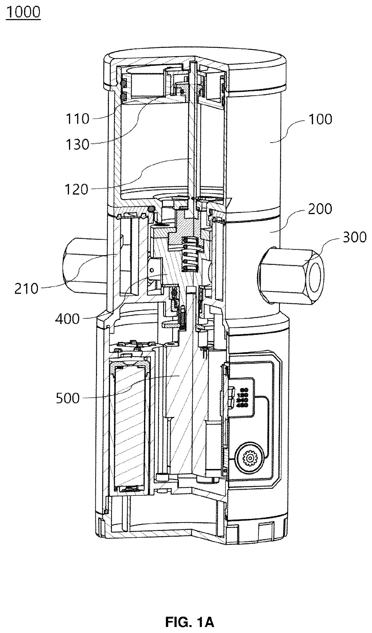
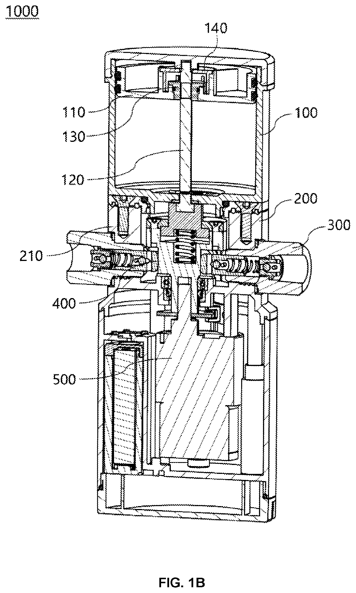
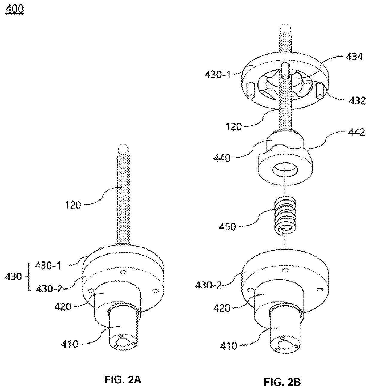
[0036]Hereinbelow, exemplary embodiments of the present invention will be described in detail with reference to the accompanying drawings. Throughout the drawings, like reference numerals will refer to like parts. Repeated descriptions and descriptions of known functions and configurations which have been deemed to unnecessarily obscure the gist of the present invention will be omitted below. Although exemplary embodiments of the present invention are described below, the invention may be embodied in many alternate forms by a person skilled in the art without departing from the spirit of the invention and should not be construed as limited to only the embodiments set forth herein.

[0037]It will be understood that when an element is referred to as being “coupled” or “connected” to another element, it can be directly coupled or connected to the other element or intervening elements may be present therebetween. In contrast, it should be understood that when an element is referred to as ...


PUM


Abstract

An oil injection apparatus includes: a storage unit extruding lubricating oil through an ejection hole formed at a lower end thereof; a discharge unit communicating with the storage through the ejection hole and discharging the lubricating oil outside according to a pumping operation; a plurality of discharge pumps arranged at regular intervals in a circumferential direction of the discharge unit and having respective first ends disposed in the discharge unit; and a driving unit rotating in a direction to sequentially press the first ends of the discharge pumps, which are disposed in the discharge unit, thereby causing the discharge pumps to perform the pumping operation in turn.

Description

REFERENCE TO RELATED APPLICATIONS[0001]This application claims the priority benefit of Korean Patent Application No. 10-2016-0162160 filed on Nov. 30, 2016, the entire contents of which are incorporated herein by reference.FIELD OF THE INVENTION[0002]The present invention generally relates to an oil injection apparatus. More particularly, the present invention relates to an oil injection apparatus that is provided at a location which requires lubricating due to mechanical friction, thereby enabling automatic injection of lubricating oil to the location.BACKGROUND OF THE INVENTION[0003]An oil injection apparatus used for a typical industrial machine, specifically at a location at which mechanical friction occurs, has become widespread and is now being used in many industrial fields. Although the use of the oil injection apparatus is increasing, many problems associated with the use of the oil injection apparatus occur in industrial sites for reasons described below.[0004]An oil injec...

Claims


Application Information

Patent Timeline
Patent Type & Authority Patents(United States)
IPC IPC(8): F16N11/08F16N7/38F16N13/14F16N13/04F16N13/06
CPCF16N13/14F16N13/04F16N11/08F16N7/385F16N2210/12F16N2210/16F16N2210/14F16N2210/18F16N2013/063F16N7/38F16N2013/205F16N13/22F16N23/00
Inventor LEE, SEUNG-HEONLEE, DEOK-BEUM
Owner KLT CO LTD
Learn More