Device and method for weighing filled capsules

a technology for weighing capsules and capsules, which is applied in the direction of instruments, packaged goods types, other domestic articles, etc., can solve the problems of increasing investment costs, limiting the throughput speed and output quantity, and high cost of weighing capsules, so as to and reduce the risk of weighing capsules

Active Publication Date: 2019-12-10
HARRO HOFLIGER VERPACKUNGSMASCHEN
View PDF10 Cites 0 Cited by
  • Summary
  • Abstract
  • Description
  • Claims
  • Application Information

AI Technical Summary

Benefits of technology

[0006]It is an object of the invention to provide a device for weighing filled capsules such that precise weighing is possible even at reduced cycle rates.
[0008]It is a further object of the invention to provide a more rapid method for weighing capsules.
[0012]Although the stopping of the capsule can take place in a form-fitting manner for example using an outfeed lever. However, the subsequent simple lying of the capsules solely under the action of static friction results in reliable reproducibility of the capsule orientation during weighing. It is possible to reliably rule out a situation in which individual capsules come to rest in an upright position rather than lying, as desired. For all capsules, the same boundary conditions thus apply during weighing. On account of the inclination according to an aspect of the invention of the receiving section of the weighing receptacle and the inclined deposition according to an aspect of the invention of the capsule thereon, the time period in which the filling trickles or flows back out of the front stopped position after the capsule has been stopped can be reduced considerably. Depending on the coordination of the individual parameters such as powder properties, inclination angle and the like, it may even be possible to achieve a situation in which the formation of a slope does not occur at all and nothing trickles back. At any rate, compared with the prior art, considerably shorter waiting times need to be maintained before reliable weighing can be carried out. It may even be possible for such waiting times to be dispensed with entirely. The actual process of weighing itself can be kept very short, such that subsequent capsules can be transported up for weighing in very short time intervals. Overall, a considerable shortening of the cycle rates and thus a corresponding increase in the output quantity can be achieved. Nevertheless, very tight mass tolerances of for example ±2 mg can be maintained during weighing.
[0013]In this case, it is necessary to find a good compromise between little movement of the filling and little tendency of the capsule to slide on the inclined support surface. Consideration should be given to the fact that high inclination angles are useful for a still behavior of the filling, while, in contrast thereto, low inclination angles of the receiving section of the weighing receptacle result in less of a tendency of the capsule deposited thereon to slide. The angle of the abovementioned inclination of the receiving section of the weighing receptacle relative to the horizontal direction is therefore advantageously in a range from 5° to 25°, inclusive, preferably in a range from 8° to 20°, inclusive, and in particular in a range from 11° to 17°, inclusive. In the angular ranges, it is possible to ensure that the capsule is held by a friction fit and maintains its intended position without sliding. Depending on the capsule geometry and trickling or flow behavior of the filling, it was also possible to observe very rapid settling in the angular ranges, and so short waiting times down to no waiting time at all was / were necessary from capsule deposition to the start of measuring. To this end, in a first preferred embodiment, the inclination angle is 17°±2°, this having been found to be a good compromise with an emphasis on little filling movement. In a second preferred embodiment, the inclination angle is 11°±2°. In this case, a reduced tendency of the capsule to slide together with a still suitably low filling movement is achieved.
[0014]In an advantageous embodiment of the invention, the capsule transporter is configured as a rotatable transport wheel, wherein the weighing receptacle has the shape of a partial circle extending in the direction of movement. The partial circle shape allows, if required, a variation in the inclination angle simply by the capsules being fed out of the capsule transporter and deposited at a slightly earlier or slightly later rotation angle of the transport wheel. In this way, the inclination angle can be adapted during weighing practically without structural changes. Furthermore, the partial circle shape makes it easier to remove the weighed capsule in a controlled manner.
[0015]In an advantageous embodiment, the receiving section is formed by two partial-surface sections, wherein the two partial-surface sections are inclined in a manner facing one another as seen in the cross section of the receiving section. In a preferred embodiment, the two partial-surface sections enclose a dihedral angle which is in a range from 120° to 60°, inclusive, and in particular is at least approximately 90°. As a result of the channel shape formed thereby, not only lateral guidance of the capsule is achieved. Rather, the two inclined partial-surface sections form from the supporting forces, a force parallelogram with mutually facing force components which, at a given inclination angle and coefficient of friction, result in an increased holding force on the capsule. The tendency of the latter to slide is reliably overcome.

Problems solved by technology

However, it has been found that the weighing carried out in such a way represents the limiting factor as regards throughput speed and output quantity.
An increase in the output quantity can only be achieved through an increase in the number of machine tracks under these conditions, this further increasing the investment costs, which are in any case already high, for the weighing device.

Method used


Image

  • Device and method for weighing filled capsules
  • Device and method for weighing filled capsules
  • Device and method for weighing filled capsules

Examples


Embodiment Construction

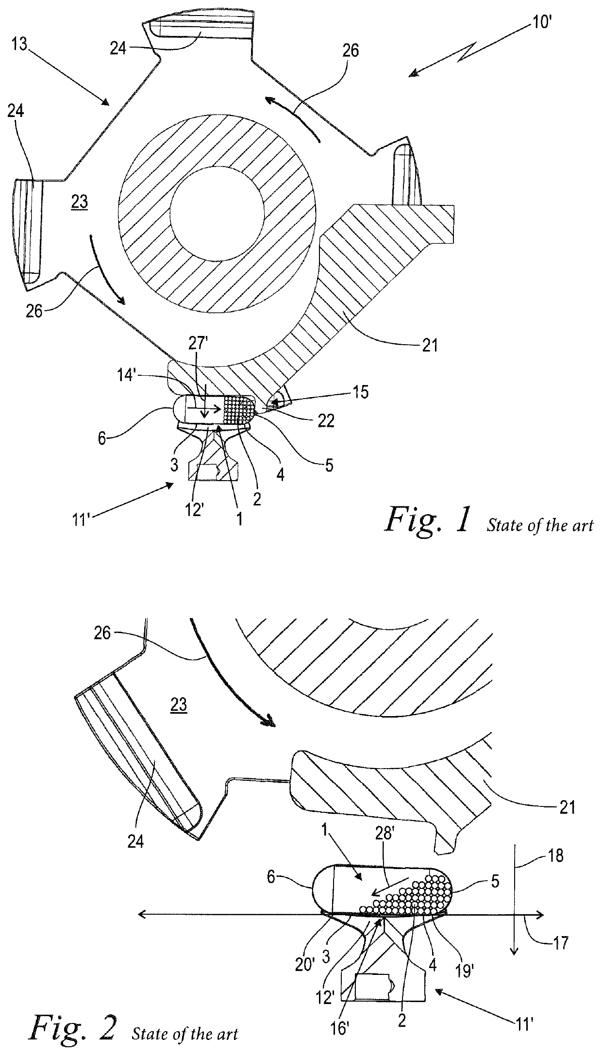
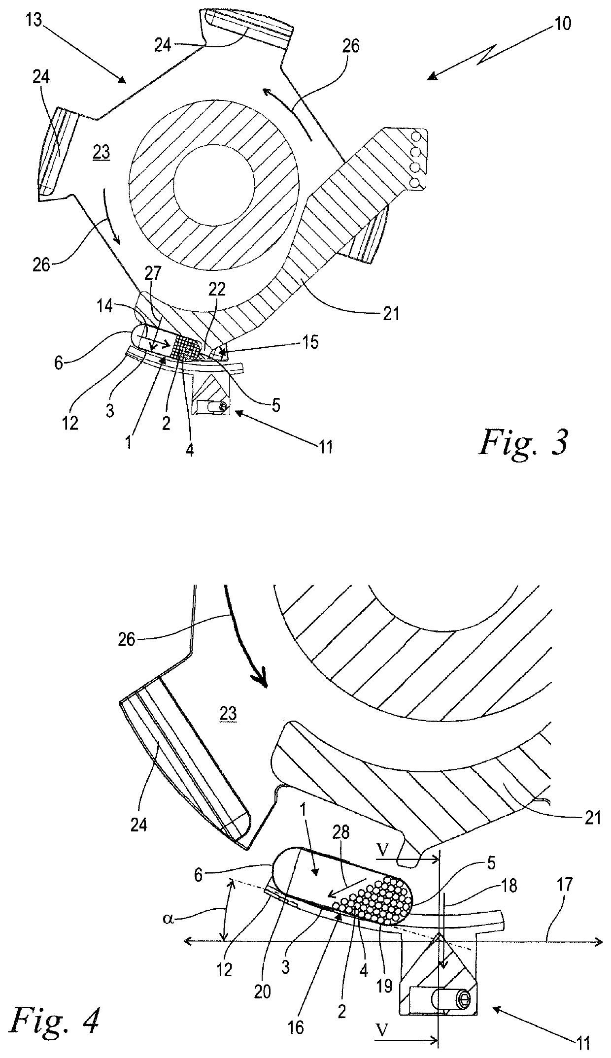
[0022]FIGS. 1 and 2 show a device 10′ for weighing capsules 1 having a filling 2 according to the prior art. FIGS. 3 and 4 show comparable views of a device 10, modified according to aspects of the invention, for the same purpose, wherein identical features are provided with the same reference signs. For the sake of simplicity, both devices 10′, 10 and the methods carried out therewith are described jointly inasmuch as the same information applies to both. Only the differences are explicitly noted. Thus, where not associated expressly with the prior art or the modification according to the invention, the following text applies to both embodiments. The devices 10, 10′ are shown in a conventional, upright operating position relative to a horizontal direction 17 and a weight force direction 18 orthogonal thereto. The weight force direction 18 corresponds to the direction of gravitational force or of gravitational acceleration.

[0023]The capsule 1 to be weighed is shown in this case for ...


PUM


Abstract

A device and a method are for weighing capsules having a filling. The device has a weighing unit having a receptacle, a transporter for transporting individual capsules to the weighing unit in a direction of movement, and a stopping device. The receiving section of the receptacle is configured as a friction support and is inclined with respect to a horizontal direction. Upon reaching the weighing unit, the capsule is stopped from moving in the movement direction via the stopping device and is deposited in the receiving section in an inclined manner such that a front end, with regard to the movement direction, of the capsule is located lower down than a rear end of the capsule, and such that the capsule comes to rest on the receptacle in this position and with regard to the direction of movement solely because of static friction. The capsule is then weighed.

Description

CROSS REFERENCE TO RELATED APPLICATION[0001]This application claims priority of European patent application no. 16 002 741.3, filed Dec. 23, 2016, the entire content of which is incorporated herein by reference.FIELD OF THE INVENTION[0002]The invention relates to a device for weighing capsules and to a method for weighing capsules via such a device.BACKGROUND OF THE INVENTION[0003]In the pharmaceutical sector and also in the dietary supplement sector, numerous preparations are filled into capsules which are intended to be taken orally. In the case of various preparations, it is important that they are prepared as a single dose in the capsule with a fixedly defined and exactly contained mass. Suitable metering devices and methods are intended to ensure that very tight mass tolerances of for example ±2 mg are maintained under the conditions of high-volume filling.[0004]Such requirements placed on the target mass are increasingly also associated with the desire for suitable testing and...

Claims


Application Information

Patent Timeline
Patent Type & Authority Patents(United States)
IPC IPC(8): G01G13/02G01G17/00G01G21/22A61J3/07B07C5/18B65B1/46
CPCG01G13/02A61J3/074B65B1/46G01G13/026G01G17/00G01G21/22A61J2200/74B07C5/18B07C2501/0081G01G21/23
Inventor KIEHN, UWEPUPPICH, THOMAS
Owner HARRO HOFLIGER VERPACKUNGSMASCHEN
Why Eureka
Try Eureka