Semiconductor device module

a technology of semiconductor devices and devices, applied in semiconductor devices, semiconductor/solid-state device details, electrical apparatus, etc., can solve the problems of reducing increasing the stress of the power device, etc., to improve the positional precision of the lead electrode, and improve the reliability of the semiconductor device module

Active Publication Date: 2019-12-17
MITSUBISHI ELECTRIC CORP
View PDF3 Cites 0 Cited by
  • Summary
  • Abstract
  • Description
  • Claims
  • Application Information

AI Technical Summary

Benefits of technology

[0010]In the semiconductor device module according to the present invention, the retainer restricts the movement of the lead electrode. Consequently, the positional precision of the lead electrode will be improved, and a clearance between the lead electrode and the semiconductor device can be appropriately maintained. Furthermore, a brazing filler metal for the lead electrode can be brazed with a favorable shape maintained, and thermal displacement of the brazing filler metal due to the heat generated when an electric current is applied to the semiconductor devices will be reduced, which can improve the reliability of the semiconductor device module.

Problems solved by technology

Thus, the challenge to obtain a favorable shape of the brazing filler metal is to improve alignment precision of a lead electrode and a power device.
In addition, disuse of the pressure sealing makes it difficult to reduce the thermal displacement of the lead electrode, which may increase the stress to the power device and reduce the reliability of the semiconductor device module.

Method used


Image

  • Semiconductor device module
  • Semiconductor device module
  • Semiconductor device module

Examples


embodiment 1

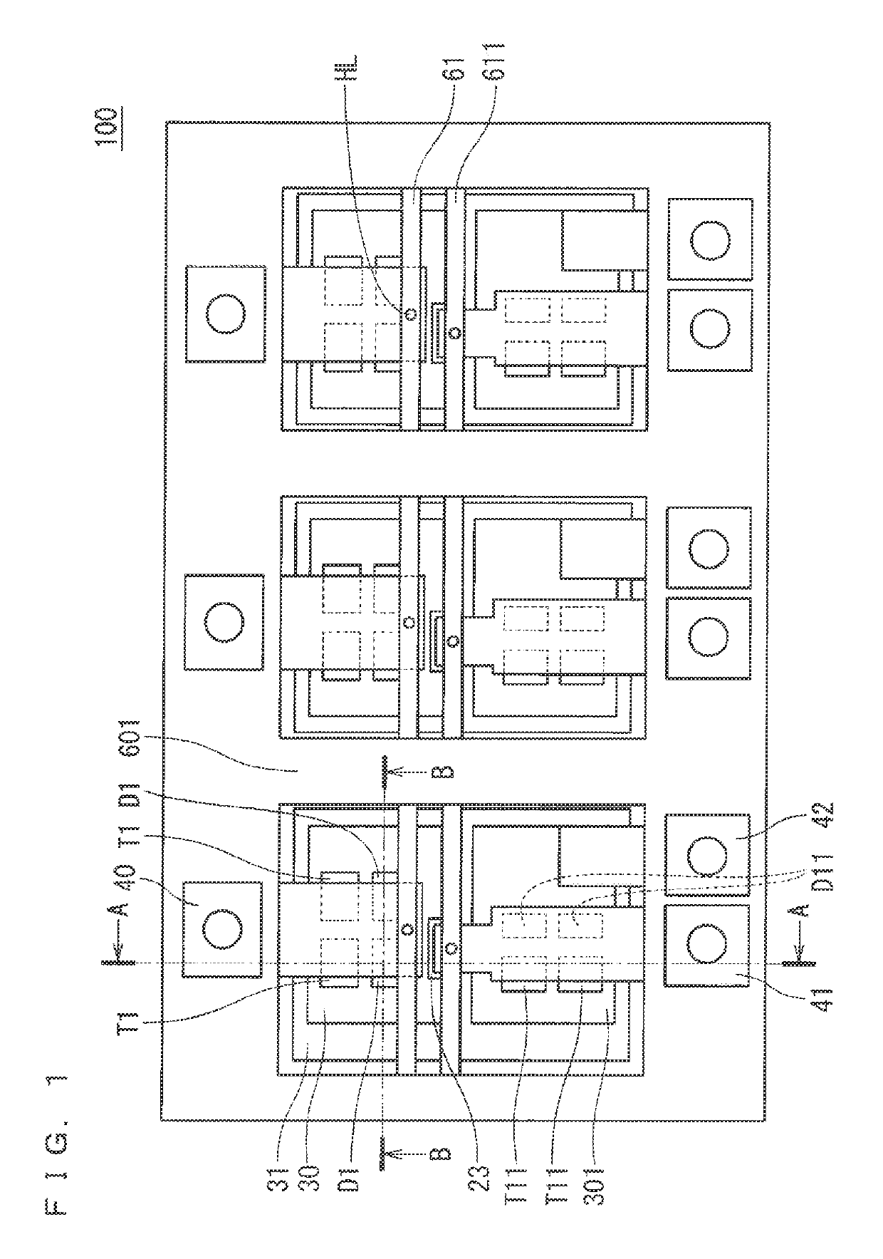
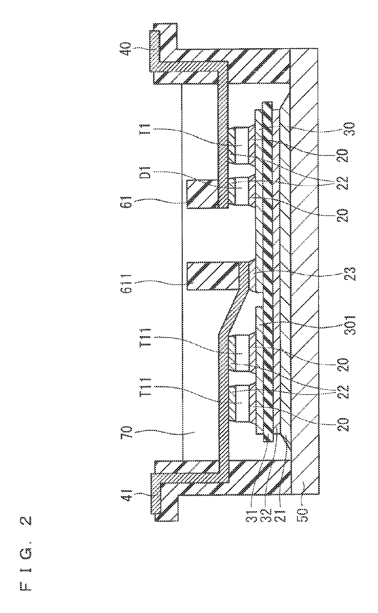
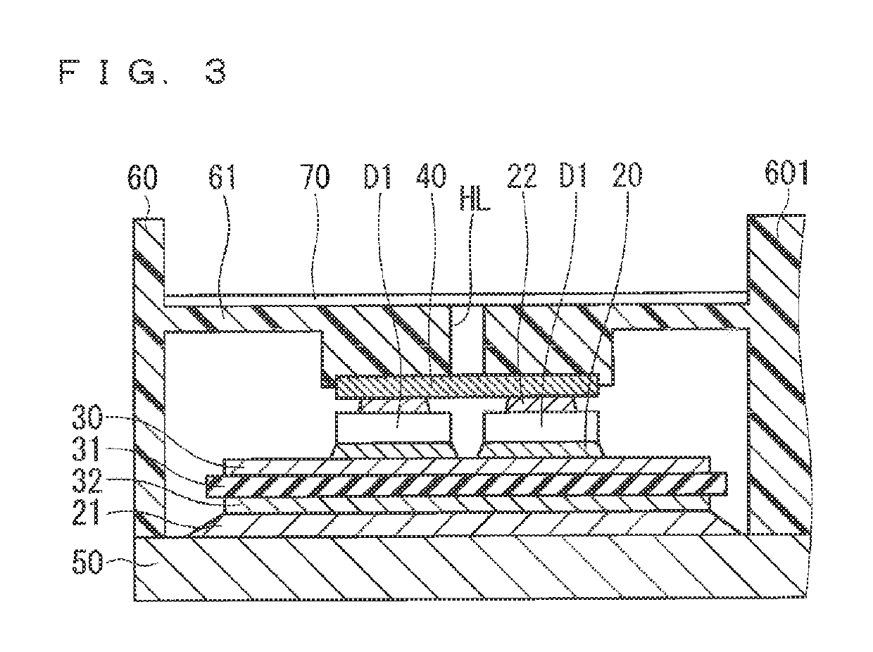
[0020]FIG. 1 is a plan view illustrating a configuration of a semiconductor device module 100 according to Embodiment 1 of the present invention. The semiconductor device module illustrated in FIG. 1 is the one that packages, as one module, power devices such as an insulated gate bipolar transistor (IGBT), a metal-oxide-semiconductor field-effect transistor (MOSFET), and a free wheeling diode (FWD). FIG. 1 illustrates a three-phase inverter as one example.

[0021]In FIG. 1, for example, circuit patterns 30 and 301 are placed on an insulating substrate 31 made of, for example, aluminum nitride (AlN), inside a resin case 60 (insulating case). Switching devices T1 and diode devices D1 are mounted on the circuit pattern 30, and switching devices T11 and diode devices D11 are mounted on the circuit pattern 301. The switching devices T1 and the diode devices D1 are each two devices connected in parallel, and the switching devices T11 and the diode devices D11 are also each two devices conne...

embodiment 2

[0070]FIG. 9 is a plan view illustrating a configuration of a semiconductor device module 200 according to Embodiment 2 of the present invention. Although the semiconductor device module illustrated in FIG. 9 is the one that packages, as one module, power devices such as an IGBT, a MOSFET, and a FWD, similarly as the semiconductor device module illustrated in FIG. 1, FIG. 9 illustrates a single-phase inverter. In FIG. 9, the same reference numerals are attached for the same structure as that of the semiconductor device module 100 described with reference to FIG. 1, and the overlapping description will be omitted.

[0071]In these days when the high-output semiconductor device modules have been sought, the number of semiconductor devices connected in parallel tends to increase, which upsizes the modules even with inclusion of the single-phase inverters.

[0072]In FIG. 9, circuit patterns 302 and 303 are placed on the insulating substrate 31. The switching devices T1 and the diode devices ...


PUM


Abstract

The present invention relates to a semiconductor device module which includes: a semiconductor device including a top electrode and a bottom electrode; a substrate on which the bottom electrode of the semiconductor device is bonded; a heat sink on which the substrate is mounted; a lead electrode through which a main current of the semiconductor device flows; an insulating case disposed to enclose the substrate; and a retainer disposed in a cantilevered manner in the insulating case, the retainer supporting the lead electrode, wherein the lead electrode has one end brazed to the top electrode of the semiconductor device, and another end side inserted into a wall of the insulating case, and the retainer is engaged on the one end of the lead electrode to restrict movement of the lead electrode.

Description

TECHNICAL FIELD[0001]The present invention relates to a semiconductor device module, and particularly to a semiconductor device module including a power device.BACKGROUND ART[0002]In recent years, high-power and downsized semiconductor device modules with high reliability have been sought as in-car power semiconductor devices. To realize these, a direct lead bonding (DLB) structure for directly bonding a power device to an external leading electrode has been introduced. Furthermore, a study has been conducted on a semiconductor device module having a direct cooling structure and combined with a finned heat sink.[0003]When the direct cooling structure is used, a structure of packaging a plurality of power devices as one module is desired to facilitate seal design of a cooling unit and also connection to an external wire.[0004]In the DLB structure, the reliability of the module is affected by the shape of a brazing filler metal for bonding a power device to a lead electrode, an amount...

Claims


Application Information

Patent Timeline
Patent Type & Authority Patents(United States)
IPC IPC(8): H01L23/48H01L23/488H01L23/053H01L23/16H01L23/36
CPCH01L23/16H01L23/488H01L23/053H01L23/36H01L23/28H01L23/48H01L25/07H01L25/18H01L2224/40H01L2924/00H01L2924/13055H01L2924/00014H01L25/072H01L2924/1305H01L2224/48091H01L2924/13091H01L23/49811H01L23/3735H01L23/24
Inventor IIZUKA, ARATAOKAMOTO, KOREHIDETSUJI, NATSUKI
Owner MITSUBISHI ELECTRIC CORP
Why Eureka
Try Eureka