Resist composition for immersion exposure and method for resist pattern formation

Inactive Publication Date: 2010-02-04
TOKYO OHKA KOGYO CO LTD
View PDF4 Cites 2 Cited by
  • Summary
  • Abstract
  • Description
  • Claims
  • Application Information

AI Technical Summary

Benefits of technology

[0019]As a result of intensive investigation, the inventors of the present invention discovered that by using a polymer compound having an acid-generating group that generates acid upon irradiation (exposure), the above object could be achieved, and they were therefore able to complete the present invention.
[0029]The present invention is able to provide a resist composition for immersion exposure and a method for resist pattern formation that enable the formation of a resist pattern of favorable shape.

Problems solved by technology

However, many factors associated with immersion exposure remain unknown, and the formation of an ultra fine resist pattern of a level suitable for actual use remains problematic.
For example, when an attempt was made to apply conventional KrF resist compositions and ArF resist compositions to immersion exposure, either patterns were unable to be formed, or even if formed, the resulting resist pattern shapes were unsatisfactory, with problems including undulations within the line patterns and roughness within the side wall surfaces of the resist pattern, so-called line edge roughness (LER).
As the miniaturization of resist patterns continues to progress, the demands for higher levels of resolution will increase, making improvements in the above shape problems more and more critical.

Method used


Image

  • Resist composition for immersion exposure and method for resist pattern formation
  • Resist composition for immersion exposure and method for resist pattern formation
  • Resist composition for immersion exposure and method for resist pattern formation

Examples


synthesis example 1

[0242]0.7 g of the monomer component (1), 10.0 g of the monomer component (2), 7.2 g of the monomer component (3), and 5.0 g of the monomer component (4) were dissolved in 100 ml of tetrahydrofuran, and 0.35 g of azobisisobutyronitrile was added. Following refluxing for 6 hours, the reaction solution was added dropwise to 1 L of n-heptane. The precipitated resin was collected by filtration and dried under reduced pressure, yielding a white resin powder. This resin was termed resin 1, and the structural formula for the resin is shown below. The weight average molecular weight (Mw) of the resin 1 was 10,600, and the polydispersity (Mw / Mn) was 1.8. Furthermore, analysis by carbon-13 nuclear magnetic resonance spectroscopy (13C-NMR) revealed a compositional ratio (molar ratio) between each of the structural units shown in the structural formula below of a:b:c:d=36.4:38.6:23.9:1.1.

example 1

[0244]100 parts by weight of the resin 1 and 0.3 parts by weight of tri-n-octylamine were dissolved in a mixed solvent of propylene glycol monomethyl ether acetate (PGMEA) and ethyl lactate (EL) (PGMEA:EL=6:4 (weight ratio)), thus yielding a positive resist composition solution with a solid fraction concentration of 5% by weight.

[0245]Subsequently, the thus obtained positive resist composition solution was evaluated in the manner described below.

[Immersion Exposure Evaluation]

[0246]An organic anti-reflective film material (product name: ARC-29, manufactured by Brewer Science Ltd.) was applied to the surface of an 8-inch silicon wafer, and the composition was then baked at 225° C. for 60 seconds, thereby forming an organic anti-reflective film with a thickness of 77 nm and completing preparation of the substrate. The positive resist composition solution obtained above was applied uniformly across the surface of this substrate using a spinner, and was then prebaked and dried on a hotp...


PUM


Abstract

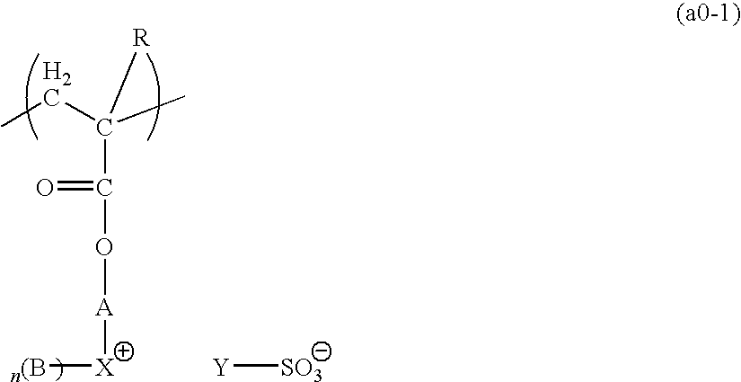
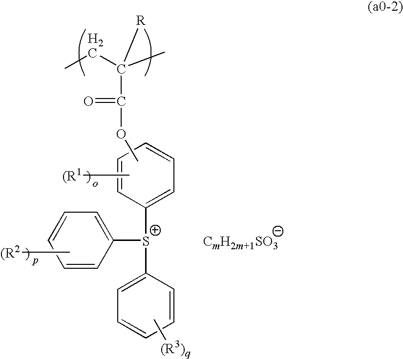
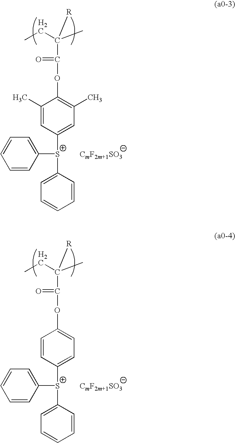
A resist composition for immersion exposure including a resin component (A) that exhibits changed alkali solubility under the action of acid, wherein the resin component (A) includes a polymer compound (A1) containing a structural unit (a0) having an acid-generating group that generates acid upon irradiation.

Description

TECHNICAL FIELD[0001]The present invention relates to a resist composition for immersion exposure that is used in a method for resist pattern formation that includes an immersion exposure step (lithography that includes an immersion exposure step is referred to as immersion lithography), and a method for resist pattern formation.[0002]Priority is claimed on Japanese Patent Application No. 2004-367971, filed Dec. 20, 2004, the content of which is incorporated herein by reference.BACKGROUND ART[0003]Lithography methods are widely used in the production of microscopic structures in a variety of electronic devices such as semiconductor devices and liquid crystal devices, and ongoing miniaturization of the structures of these devices has lead to demands for further miniaturization of the resist patterns used in these lithography processes. With current lithography methods, using the most up-to-date ArF excimer lasers, fine resist patterns with a line width of approximately 90 nm are able...

Claims


Application Information

Patent Timeline
IPC IPC(8): G03F7/20G03F7/004
CPCG03F7/0045G03F7/2041G03F7/0397G03F7/004G03F7/0047G03F7/039G03F7/0392H01L21/027H01L21/0271
Inventor TSUJI, HIROMITSUMATSUMARU, SHOGO
Owner TOKYO OHKA KOGYO CO LTD
Why Eureka
Try Eureka