
Modular charging system and method of delivering electric power through the same

a technology of module charging and electric power, which is applied in the direction of coupling device connection, liquid/fluent solid measurement, instruments, etc., can solve the problems of increasing power demand of portable consumer electronic devices, decreasing device price, and many electronic devices carried by consumers cannot go an entire day without the battery

Active Publication Date: 2019-12-17
GROUP DEKKO
View PDF19 Cites 0 Cited by
  • Summary
  • Abstract
  • Description
  • Claims
  • Application Information

AI Technical Summary

Benefits of technology

The system provides efficient and convenient DC power delivery to multiple devices, reducing the need for bulky converters and allowing flexible placement in public areas, while integrated 'smart' features manage power distribution and protection.

Problems solved by technology

Such devices have become increasingly common due to the price of the devices decreasing while the functionality of the devices increases.
Unfortunately, the technology for rechargeable batteries powering portable consumer electronic devices has not kept pace with the growing power demands of the devices.
As such, many electronic devices carried by consumers cannot go an entire day without the battery needing to be recharged.
This has made power outlets in public areas where consumers may spend a significant amount of time, such as travel hubs and hospitals, scarce commodities that people often crowd around to recharge their devices.
Many large public areas do not provide sufficient access to electrical power for everyone wishing to recharge their electronic devices, especially in convenient locations that are accessible from areas with seating.
Even in high-traffic public areas that do provide electrical outlets, many of the outlets are placed in peripheral walls of the area, due to electrical wiring being hidden in the walls, and may not be accessible from seating areas due to the distance between the seating area and the outlet.
The adapter “bricks” are, as their name implies, fairly large, non-pliable and inconvenient to carry, especially compared to USB cables.

Method used


Image

  • Modular charging system and method of delivering electric power through the same
  • Modular charging system and method of delivering electric power through the same
  • Modular charging system and method of delivering electric power through the same

Examples


Embodiment Construction

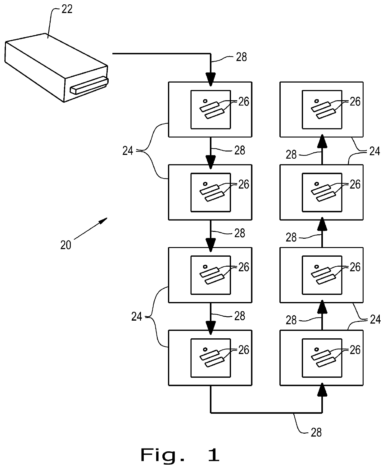
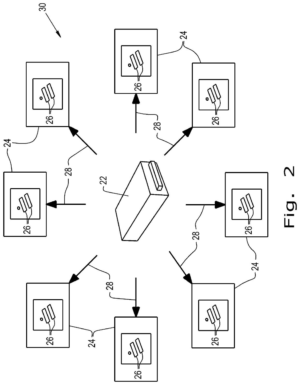
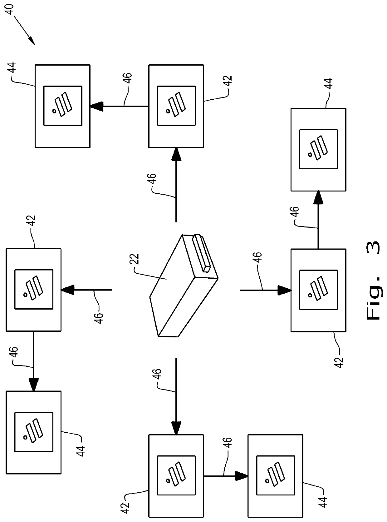
[0029]Referring now to the drawings, and more particularly to FIG. 1, there is shown a power delivery system 20 which generally includes a power supply 22, which can also be referred to as a power adapter or converter, connected to a plurality of power delivery units 24, shown as universal serial bus (USB) chargers each having two USB outlet port connections 26, in series. While eight USB chargers 24 are shown being connected in series, it is contemplated that a smaller or larger number of USB chargers 24 could be connected in series to the power supply 22, which will be described further herein. Further, the power delivery units 24 can be any type of assembly that allows for a connected device to receive electrical power from the power supply 22, and does not need to necessarily have USB connections as the outlet ports 26. The power supply 22, as shown, can be any type of power supply that can provide direct current (DC) power to the USB chargers 24. This delivery of DC power to th...


PUM


Abstract

A power delivery system includes: an AC-to-DC power supply configured to output initial DC power; a first power delivery unit connected to the power supply and having at least one output port, the first power delivery unit being configured as a DC-to-DC power converter to provide converted DC power through the at least one output port, the converted DC power having a different voltage and / or a different current than the output initial DC power; and a second power delivery unit connected to the power supply or the first power delivery unit through an input port and having at least one output port, the second power delivery unit being configured as a DC-to-DC power converter to provide an output DC power through the at least one output port which has a different voltage and / or a different current than the power received through the input port.

Description

CROSS REFERENCE TO RELATED APPLICATIONS[0001]This is a continuation of PCT application No. PCT / US2016 / 026670, entitled “MODULAR CHARGING SYSTEM AND METHOD OF DELIVERING ELECTRIC POWER THROUGH THE SAME”, filed Apr. 8, 2017, which claims priority from U.S. provisional patent application Ser. No. 62 / 145,194, entitled “MODULAR CHARGING SYSTEM AND METHOD OF DELIVERING ELECTRIC POWER THROUGH THE SAME”, filed Apr. 9, 2015, which are incorporated herein by reference.BACKGROUND OF THE INVENTION[0002]1. Field of the Invention[0003]The present invention relates to power supply systems, and, more particularly, to power supply systems for portable electronic devices.[0004]2. Description of the Related Art[0005]In recent years, the number of portable electronic devices regularly carried and used by consumers has increased dramatically. Specifically, “smart” cellular phones and wearables, such as watches, have become increasingly common in society. Such devices have become increasingly common due ...

Claims


Application Information

Patent Timeline
Patent Type & Authority Patents(United States)
IPC IPC(8): H02J7/00G06F1/26H02J7/02H01R31/02H02M1/00
CPCG06F1/263H02J7/0013H02J7/0042G06F1/266H02J7/022H01R31/02H02M1/00H02M3/04H02J7/02H02J7/00
Inventor HAYES, DANIELLEE, KUNVICHET
Owner GROUP DEKKO
Learn More