Check patentability & draft patents in minutes with Patsnap Eureka AI!

Method and device for evaluating the quality of a component produced by means of an additive laser sintering and/or laser melting method

a technology of additive laser sintering and laser melting, which is applied in the direction of additive manufacturing processes, instruments, optical radiation measurement, etc., can solve the problems of large inspection effort, time-consuming and cost-intensive, and inability to continuously monitor all relevant process parameters a priori, and achieves low readout noise, high image rate, and rapid and detailed inspection.

Active Publication Date: 2019-12-31
MTU AERO ENGINES GMBH
View PDF41 Cites 4 Cited by
  • Summary
  • Abstract
  • Description
  • Claims
  • Application Information

AI Technical Summary

Benefits of technology

[0003]The object of the present invention is to create a method for evaluating the quality of a component produced by means of an additive laser sintering and / or laser melting method, said method enabling an improved evaluation of the quality of the produced component. Another object of the invention is to create a suitable device for carrying out such a method.

Problems solved by technology

However, laser sintering and melting methods have not been used so far for serial production of components for aircraft engines.
In addition, a process authorization, a prerequisite of which is the monitoring of diverse process parameters, such as, for example, the laser power as well as the nature and state of the powdered material and the like, is required, in particular, for the use of components that are produced by additive laser methods and are subject to high loads.
The inspection effort that thereby ensues is great and correspondingly time-consuming and cost-intensive.
Furthermore, a continuous monitoring of all relevant process parameters is often not possible a priori.

Method used


Image

  • Method and device for evaluating the quality of a component produced by means of an additive laser sintering and/or laser melting method
  • Method and device for evaluating the quality of a component produced by means of an additive laser sintering and/or laser melting method
  • Method and device for evaluating the quality of a component produced by means of an additive laser sintering and/or laser melting method

Examples


Embodiment Construction

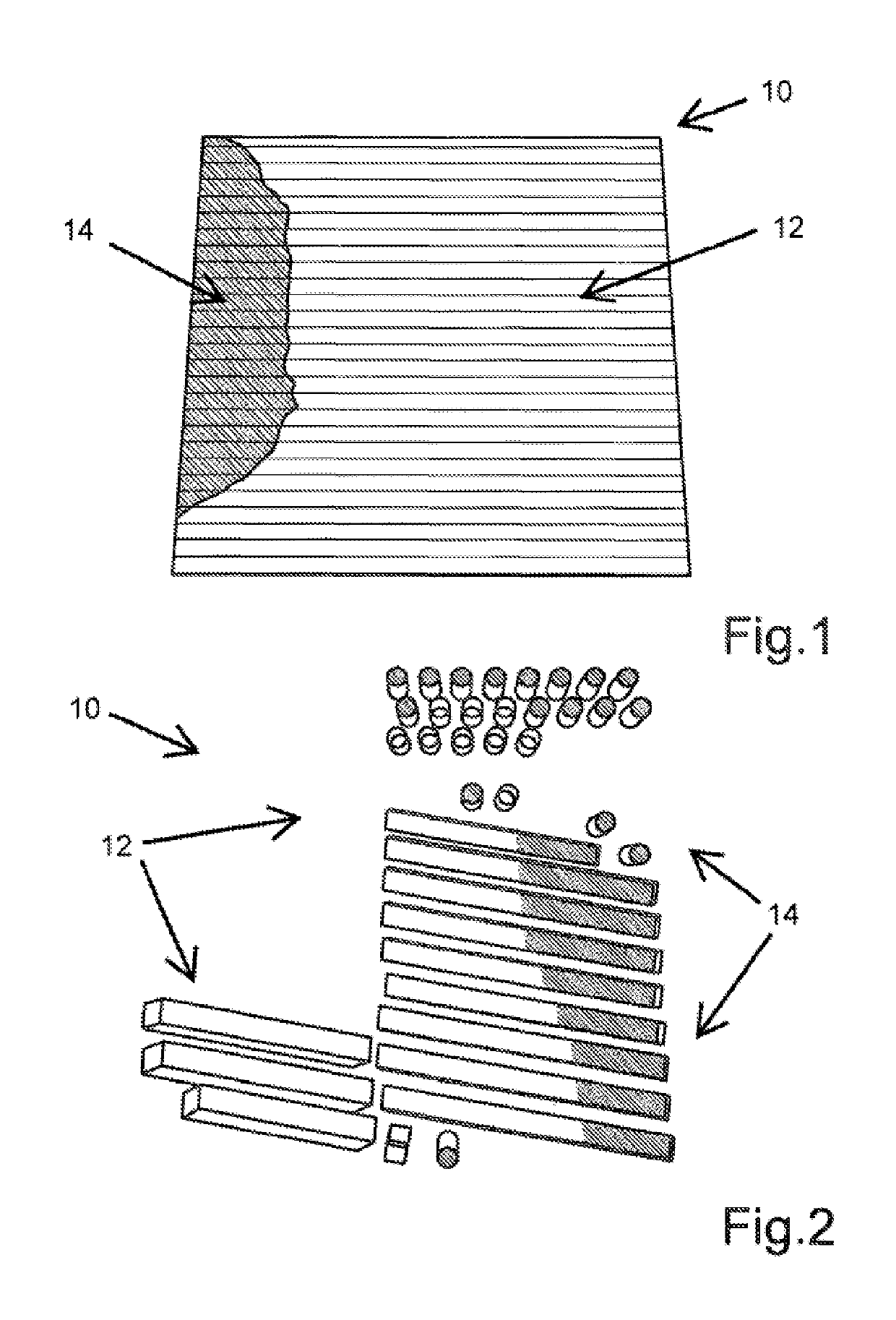
[0026]FIG. 1 shows a thermographic plan view of a layer of a component 10 for an aircraft engine, said component 10 being manufactured from a corresponding material powder by using an additive laser sintering or laser welding method, which is known as such. On the one hand, a large-area region 12, which has a uniform temperature distribution, and, on the other hand, a smaller region 14, which, in comparison to the region 12, has a lower temperature, can be seen. The cross strips of the region 12 symbolize, in addition, a direction of layering during the additive manufacturing of the component 10. The temperatures are characterized in this case on the basis of spatially resolved gray-scale values, so that the region 14 appears darker than the region 12. The temperature values can be determined by thermographic methods and compiled in a first data set for each measured component coordinate, for example. In the process, the number of data points can be optimally adjusted depending on t...


PUM

PropertyMeasurementUnit
temperatureaaaaaaaaaa
surface areaaaaaaaaaaa
volumeaaaaaaaaaa

Abstract

A method for evaluating the quality of a component produced by means of an additive laser sintering and / or laser melting method, in particular a component for an aircraft engine comprises at least the steps of providing a first data set, which comprises spatially resolved color values, which each characterize the temperature of the component at an associated component location during the laser sintering and / or laser melting of the component, providing a second data set, which comprises spatially resolved color values corresponding to the first data set, which color values each characterize the temperature of a reference component at an associated reference component location during the laser sintering and / or laser melting of the reference component.

Description

BACKGROUND OF THE INVENTION[0001]The invention relates to a method for evaluating the quality of a component produced by means of an additive laser sintering and / or laser melting method, in particular a component for an aircraft engine. The invention further relates to a device for carrying out a method of this type.[0002]Additive laser sintering and laser melting methods for the manufacture of components, such as, for example, components for aircraft engines, are already known as such from DE 10 2004 017 769 B4, for example. In selective laser melting, thin layers of powder of the material or materials used are placed on a construction platform and locally melted and solidified by using one or a plurality of laser beams. The construction platform is then lowered and another layer of powder is applied and again locally solidified. This cycle is repeated until the finished component is obtained. The finished component can then be further processed as needed or immediately used. In se...

Claims


Application Information

Patent Timeline
Patent Type & Authority Patents(United States)
IPC IPC(8): G01J5/00B22F3/105G01N21/35G01N21/27B29C64/153G01N21/17B33Y40/00B33Y30/00B33Y10/00
CPCG01N21/27G01N21/35B29C64/153B22F3/1055B22F2003/1057B33Y10/00B33Y40/00G01N2021/1765B33Y30/00G01N25/72B29C64/393B33Y50/02B22F2999/00Y02P10/25B22F10/28B22F10/36B22F10/38B22F10/85B22F12/90B22F2203/11B22F10/00
Inventor HESS, THOMASZENZINGER, GUNTERSATZGER, WILHELM
Owner MTU AERO ENGINES GMBH
Features
  • R&D
  • Intellectual Property
  • Life Sciences
  • Materials
  • Tech Scout
  • Unparalleled Data Quality
  • Higher Quality Content
  • 60% Fewer Hallucinations
Learn More