Combustion apparatus

a technology of combustion apparatus and burner body, which is applied in the direction of combustion types, water heaters, burners, etc., can solve the problems of auxiliary parts of the burner body, such as the check valve, to be subjected to heat damage, and the solution, however, becomes higher in cost, so as to achieve cost reduction, increase the thermal insulation performance of the packing, and reduce the effect of overheating the burner body

Active Publication Date: 2020-01-07
RINNAI CORP
View PDF16 Cites 5 Cited by
  • Summary
  • Abstract
  • Description
  • Claims
  • Application Information

AI Technical Summary

Benefits of technology

[0011]For that reason, in this invention, preferably, an outer circumference of the combustion plate flange part is positioned on an inner side of an outer circumference of the body flange part. The connection flange part and the packing respectively have protruded parts which protrude outward beyond the outer circumference of the combustion plate flange part, and a combustion box seal part is disposed at the protruded part of the packing so as to be compressed, as a result of the fastening operation, between the protruded part of the connection flange part and the body flange part. According to this arrangement, the single packing can secure not only the sealing performance between the combustion plate flange part and the body flange part but also the sealing performance between the connection flange part and the body flange part. The combustion exhaust gas can be prevented from leaking outside, to the advantage from the cost-wise point of view

Problems solved by technology

As a consequence, an auxiliary part of the burner body, such as a check valve to be disposed in an inlet port to the burner body, will be subjected to a bad effect due to heat.
This solution, however, becomes higher in cost.

Method used


Image

  • Combustion apparatus
  • Combustion apparatus
  • Combustion apparatus

Examples


Embodiment Construction

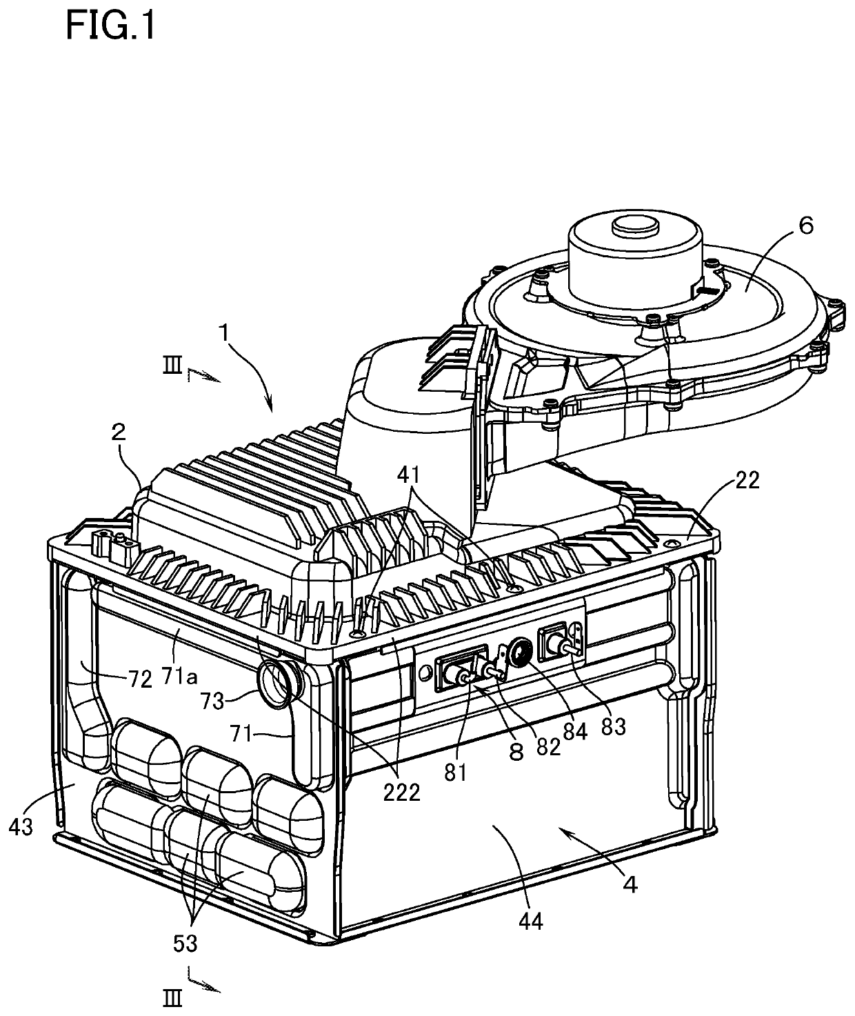
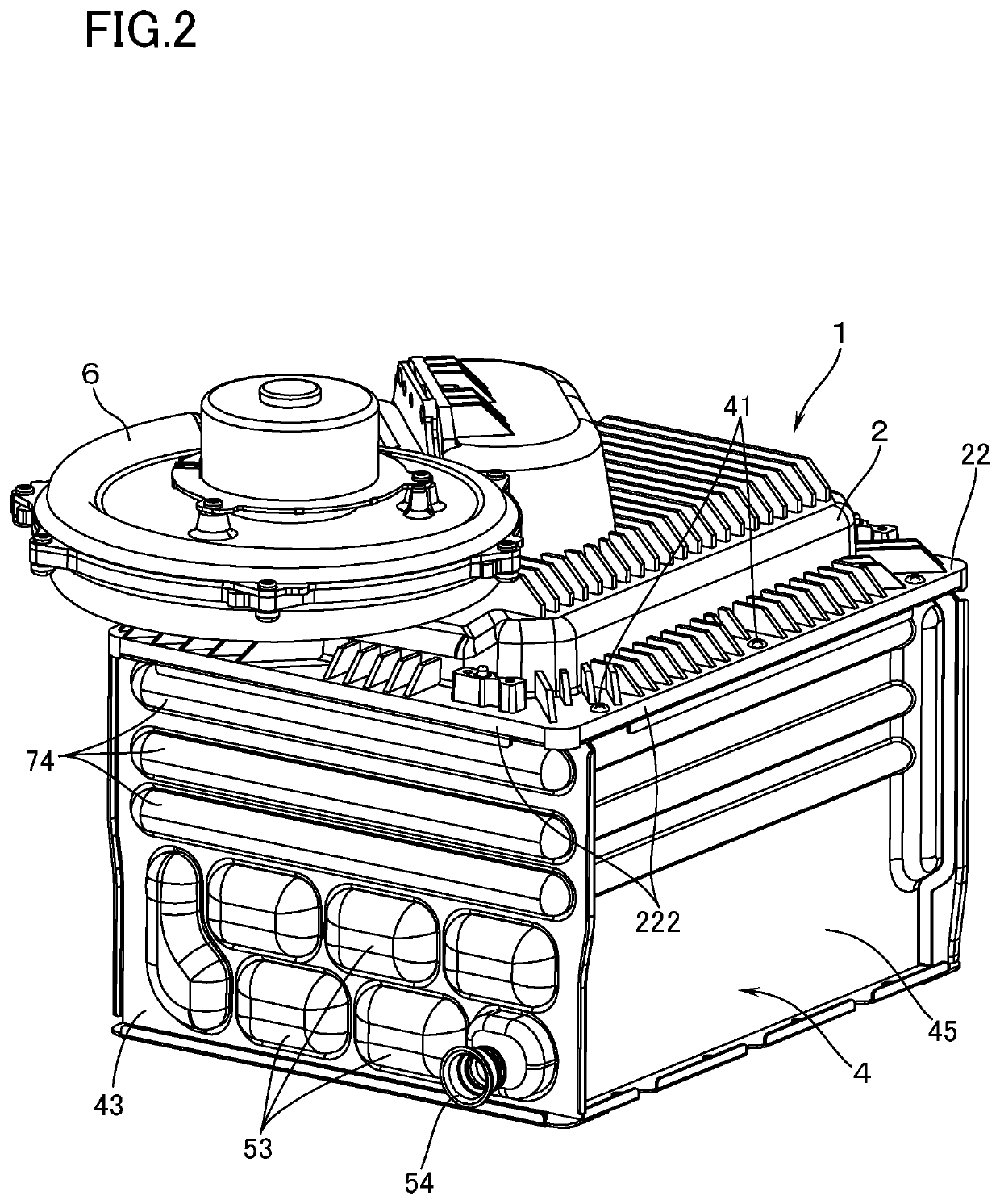
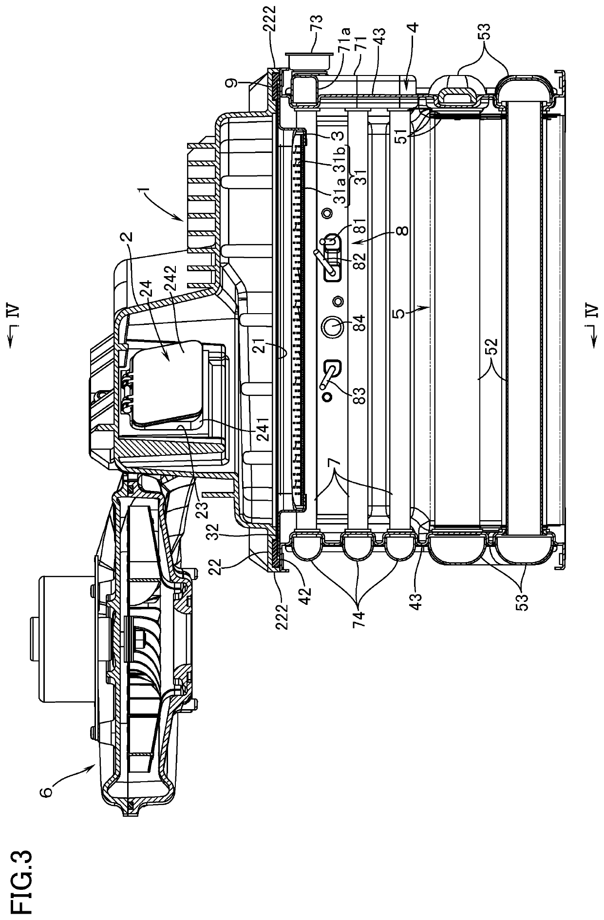
[0020]With reference to FIGS. 1 through 4, a combustion apparatus according to an embodiment of this invention is provided with: a burner 1 made up of a burner body 2 which is supplied inside thereof with air-fuel mixture (mixture gas of fuel gas and primary air), and a combustion plate 3, made by a sheet metal, which covers a downward open surface 21 of the burner body 2; and a combustion box 4 which has, at an upper end, a connection flange part 42 to be coupled, with machine screws 41, to a body flange part 22 which encloses the open surface 21 of the burner body 2. The combustion box 4 contains, inside thereof, a heat exchanger 5 for supplying hot water.

[0021]The burner body 2 has opened therein an inlet port 23 to which is connected a fan 6 for supplying air-fuel mixture. The inlet port 23 has mounted therein a check valve 24 which prevents, at the time of fan stopping, the air-fuel mixture staying inside the burner body 2 from flowing back toward the fan 6. The check valve 24 ...


PUM


Abstract

A combustion apparatus includes a burner having a sheet-metal combustion plate which covers an open surface of a burner body; and a combustion box having a connection flange part to be coupled to a body flange part enclosing the open surface of the burner body, and is equipped with a cooling means for cooling the combustion box, an arrangement is made that overheating of the burner body due to heat transmission from the combustion plate can be prevented, even without enhancing thermal insulation performance of a packing to be interposed between a combustion plate flange part and the body flange part. The connection flange part is kept in direct contact with the combustion plate flange part and, coupled to the body flange part. The packing is provided with: a combustion plate seal part to be pressed under pressure against the combustion plate flange part; and a combustion box seal.

Description

[0001]This application is a national phase entry under 35 U.S.C. § 371 of PCT Patent Application No. PCT / JP2016 / 004445, filed on Oct. 3, 2016, which claims priority under 35 U.S.C. § 119 to Japanese Patent Application No. 2015-206591, filed Oct. 20, 2015, both of which are incorporated by reference.TECHNICAL FIELD[0002]The present invention relates to a combustion apparatus provided with: a burner made up of a burner body which is supplied therein with air-fuel mixture, and a sheet-metal combustion plate which covers an open surface of the burner body and has an ejection part for the air-fuel mixture; and a combustion box which has, at one end, a connection flange part to be coupled, by a fastening operation, to a body flange part enclosing the open surface of the burner body, and which contains therein a heat exchanger.BACKGROUND ART[0003]As this kind of combustion apparatus, there is known an apparatus from patent document 1 in which, in order to improve the heat resistivity of th...

Claims


Application Information

Patent Timeline
Patent Type & Authority Patents(United States)
IPC IPC(8): F23D14/14F24H9/18F24H9/00F23D14/02F23D14/78F23M5/08F24H1/12F24H9/20
CPCF23M5/08F23D14/78F23D14/14F24H9/1836F24H9/1818F24H9/0026F24H9/0015F23D14/02F24H9/1845F24H1/124F23B2700/003F24H2250/02F24H2230/00F24H9/2035F23D14/145F24H9/18
Inventor OJIRO, TAKASHI
Owner RINNAI CORP
Why Eureka
Try Eureka