Method and apparatus for collecting waste heat of exhaust gas and reducing white smoke

a technology of exhaust gas and waste heat, which is applied in the direction of heat recovery, greenhouse gas reduction, combustion types, etc., can solve the problems of corroding the peripheral facility, generating complaints of the population, and high installation cost, so as to reduce the white smoke, reduce the maintenance cost, and remove the visual pollution factor

Active Publication Date: 2020-01-07
LEE DONG HOON
View PDF25 Cites 0 Cited by
  • Summary
  • Abstract
  • Description
  • Claims
  • Application Information

AI Technical Summary

Benefits of technology

[0038]As described above, the present invention has effects of solving the pollution problem due to the water fall around the funnel by collecting the moisture and latent heat by contacting the exhaust gas and the solution containing the hydroscopic salts and by suppressing the white smoke discharged through the funnel, and of removing the visual pollution factor, and of having low maintenance cost, and of collecting the waste heat effectively, and of raising the economical efficiency.

Problems solved by technology

In addition, the water drop which is the drop of water which has comparatively low gravity is not diffused but falls down to a certain distance from the funnel while forming the white smoke which is the steam bane, and the fallen water drop corrodes the peripheral facility and generates the complain of the population.
Conventionally, in case of wet removing the toxic gas generated at the polluted material discharge facility, to prevent the white smoke from being generated through the funnel, the atmosphere among the exhaust gas is removed by reducing the relative humidity of the exhaust gas by mixing the high temperature air from the outside or directly heating the exhaust gas by installing the burner at the funnel, however, the former has a problem of very high installation cost, and the latter has a problem of high maintenance cost according to the fuel consumption.
However, these patent documents not only include complicated facility (wet type dust collection facility), etc. but also still have not appropriately solved the problem of the white smoke.
In addition, these patent documents remain at the level of the conventional heat exchange of the waste heat of the exhaust gas and there is a tendency that it is not efficient in view of the energy utilization.

Method used


Image

  • Method and apparatus for collecting waste heat of exhaust gas and reducing white smoke

Examples


embodiment 1

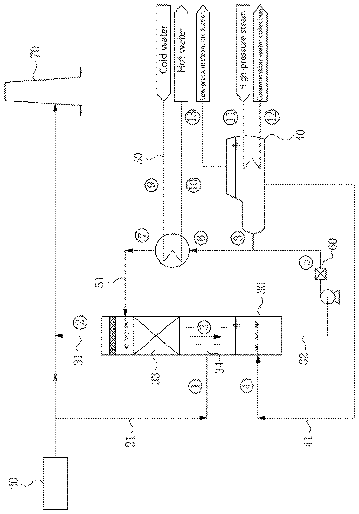
[0065]In the present embodiment, the degree of collection of waste heat of the exhaust gas and reduction of the white smoke was confirmed by using a simulation test apparatus such as FIG. 1.

[0066]Table 1 shown below show the phase (liquid phase or gas phase), temperature, pressure and flow speed of each stream of the solution containing the exhaust gas or the hydroscopic salts and the concentration of the hydroscopic salts (hereinafter referred to as “concentration”) in the solution containing the hydroscopic salts in the simulation test apparatus such as FIG. 1. For the hydroscopic salts, calcium nitrate was used.

[0067]

TABLE 1Stream TemperaturePressureFlow SpeedConcentrationNo.Phase(° C.)(kg / cm2)(kg / h)(weight %){circle around (1)}114—12.373—②55—11.291—③77—62.80064④130—14.10070⑤86—76.90065⑥86—61.70065⑦53—61.70053⑧86—15.20065⑨49—49.800—⑩72—49.800—⑪1403.61.930—⑫1403.61.930—⑬1302.51.090—

[0068]In the table 1, stream ① contains about 13.2 weight % of steam, and stream ② contains about 3....


PUM


Abstract

The present invention provides a method for collecting waste heat of exhaust gas and reducing white smoke, and an apparatus to which the method can be easily applied, the method comprising the steps of: introducing exhaust gas from an exhaust gas supply source including high-temperature steam to a heat and moisture exchange unit, collecting latent heat of the steam contained in the exhaust gas by making contact between the exhaust gas and a solution containing hydroscopic salts, condensing the collected latent heat, and discharging the processed exhaust gas to the outside of the heat and moisture exchange unit; and concentrating, cooling, and circulating the solution containing the hydroscopic salts by discharging, to a lower part of the heat and moisture exchange unit, a mixture of the solution containing the hydroscopic salts and condensation water.

Description

TECHNICAL FIELD(a) Technical Field[0001]The present disclosure relates to a method and apparatus for collecting waste heat of exhaust gas and reducing white smoke.(b) Background Art[0002]In general, since an incinerator, metal melting furnace, boiler, wet type devulcanization facility, etc. which are facilities of discharging atmospheric pollution material discharge the high temperature exhaust gas containing the high concentration pollution material to the atmosphere during operation, mainly an absorption tower (wet type dust collection facility) for removing the toxic material by injecting an aqueous solution to remove the pollution material included in such exhaust gas has been installed and used.[0003]In this wet type dust collection facility, the water is sprayed to the discharged high temperature exhaust gas, and accordingly, the exhaust gas at the exit is discharged to the atmosphere through the funnel in the condition of high temperature high humidity (saturated). At this ti...

Claims


Application Information

Patent Timeline
Patent Type & Authority Patents(United States)
IPC IPC(8): F24H8/00F23J15/06
CPCF23J15/06F24H8/00Y02E20/363Y02B30/102Y02P80/152F23J2219/70Y02B30/00Y02E20/30Y02P80/15F23J15/00F23G5/46
Inventor LEE, DONG HOON
Owner LEE DONG HOON
Why Eureka
Try Eureka