Wall mounted rail system

a rail system and wall mount technology, applied in the direction of ducting arrangement, heating types, lighting and heating equipment, etc., can solve the problems of sloppy extension cord use, potential fire or tripping hazards, and frustration for users trying to locate or access outlets

Active Publication Date: 2020-01-14
JAIN SANJEEV
View PDF7 Cites 2 Cited by
  • Summary
  • Abstract
  • Description
  • Claims
  • Application Information

AI Technical Summary

Problems solved by technology

Electrical outlets, USB outlets, and HVAC vents are often located in inconvenient places within a home or office or there are too few within a room to accommodate the needs of a household or business.
In some cases, an extension cord must be used in order to reach the outlet, leading to potential fire or tripping hazards.
Further, a room appears sloppy with extension cords strewn thereabout.
Outlets may be blocked by furniture, causing frustration for a user trying to locate or access the outlet.
In addition, HVAC ducts may be blocked by furniture, causing an inefficient airflow within a room.

Method used


Image

  • Wall mounted rail system
  • Wall mounted rail system
  • Wall mounted rail system

Examples


Embodiment Construction

[0016]Reference is made herein to the attached drawings. Like reference numerals are used throughout the drawings to depict like or similar elements of the wall mounted rail system. For the purposes of presenting a brief and clear description of the present invention, the preferred embodiment will be discussed as used for dispersing air flow and providing additional electric ports throughout the room. The figures are intended for representative purposes only and should not be considered to be limiting in any respect.

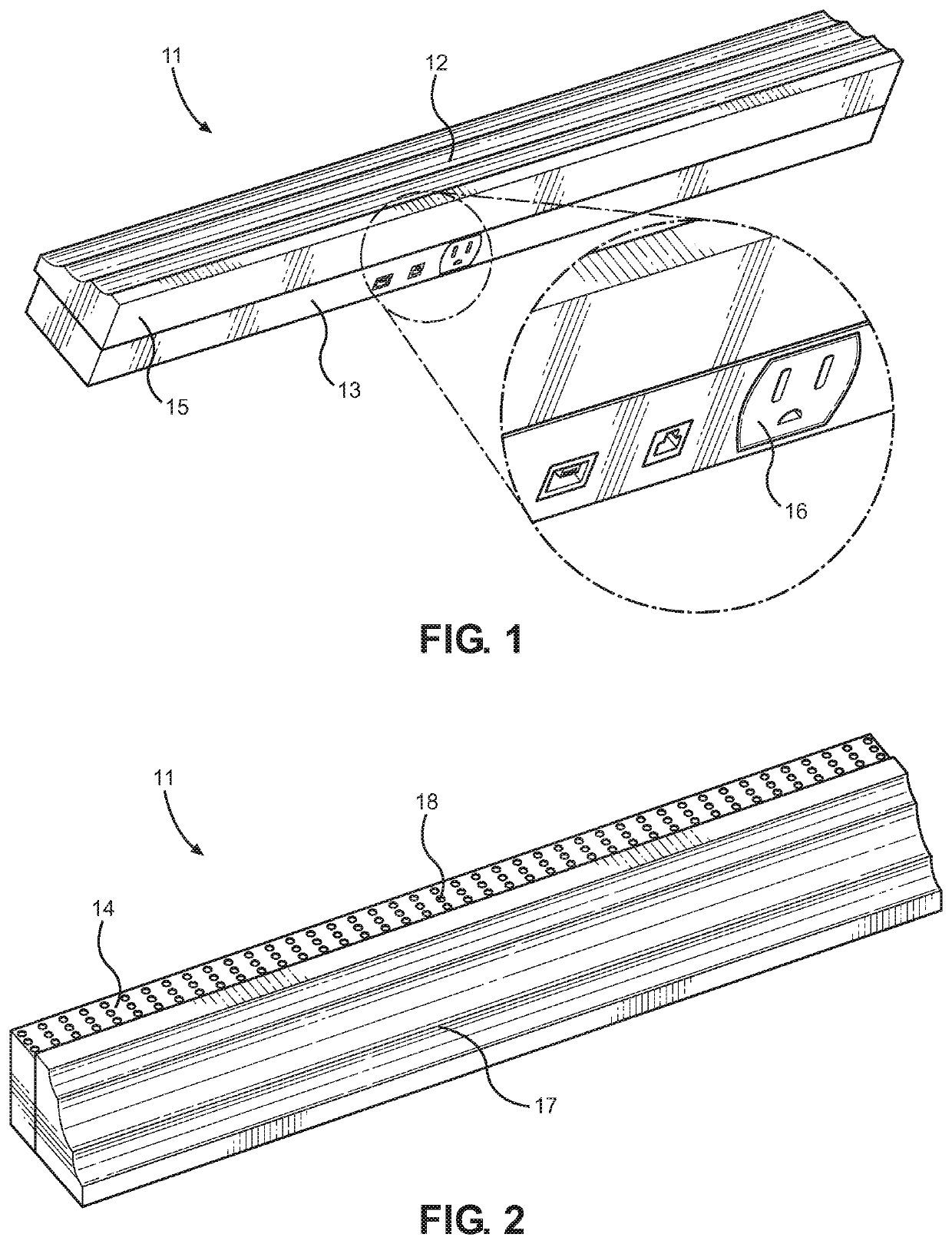
[0017]Referring now to FIGS. 1 and 2, there is shown a bottom perspective view and a top perspective view of an embodiment of the wall mounted rail system, respectively. The wall mounted rail system 11 comprises a first rail 12 having a front surface and an opposing rear surface. The front surface comprises a bottom face 13, a top face 14, and a front face 15, wherein the bottom and top face 13, 14 are parallel to one another and each perpendicular to the front face 15. ...


PUM


Abstract

A wall mounted rail system for providing additional air flow and electrical outlets to a room. The system includes a first rail removably securable to a second rail, wherein each rail includes a front surface and a rear surface. The rear surface can secure to a wall and a decorative molding, such as chair rail molding, is secured to the front surface. A plurality of ports are disposed on a bottom face of the front surface and can supply power to a device connected to each port. Further, each port is electrically connected to one another. Tubing extends through an interior volume of each rail and plurality of apertures are disposed on a top face of the front surface thereof. Each aperture is in fluid communication with the tubing to allow air to flow from the tubing, through the apertures, and into the room.

Description

CROSS REFERENCE TO RELATED APPLICATION[0001]This application claims the benefit of U.S. Provisional Application No. 62 / 624,904 filed on Feb. 1, 2018. The above identified patent application is herein incorporated by reference in its entirety to provide continuity of disclosure.BACKGROUND OF THE INVENTION[0002]The present invention relates to wall moldings. More specifically, the present invention provides a wall mounted rail system that supplies additional air flow and electrical outlets throughout a room.[0003]Electrical outlets, USB outlets, and HVAC vents are often located in inconvenient places within a home or office or there are too few within a room to accommodate the needs of a household or business. In some cases, an extension cord must be used in order to reach the outlet, leading to potential fire or tripping hazards. Further, a room appears sloppy with extension cords strewn thereabout. Outlets may be blocked by furniture, causing frustration for a user trying to locate ...

Claims


Application Information

Patent Timeline
Patent Type & Authority Patents(United States)
IPC IPC(8): H02G3/12F24F13/02H02G3/10E04F19/02F24F13/06E04F19/04
CPCE04F19/026E04F19/0459H02G3/128H02G3/10F24F13/0227F24F13/06E04F2019/044H02G3/0425
Inventor JAIN, SANJEEV
Owner JAIN SANJEEV
Why Eureka
Try Eureka