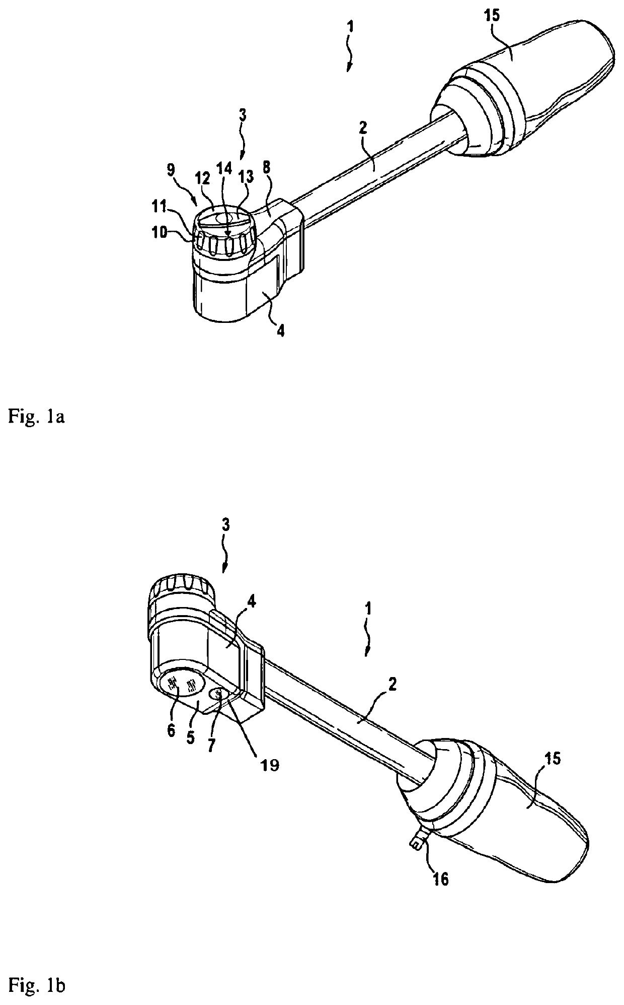
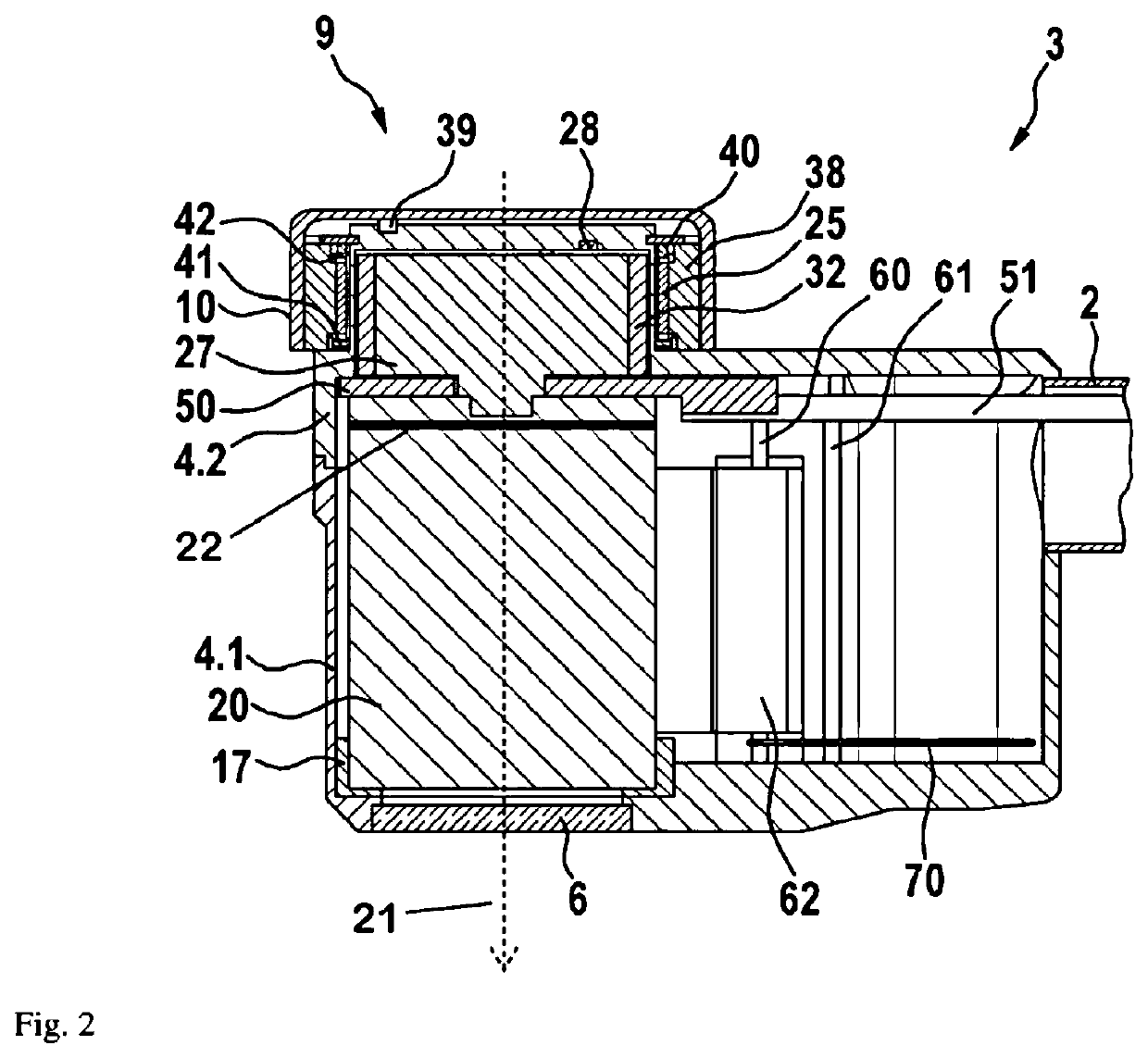
Endoscope (or exoscope) with a rotatably arranged electronic image recorder
an endoscope and electronic image recorder technology, applied in the field of endoscopes or exoscopes, can solve the problems of difficult or impossible observation for observers, and the above-described arrangement is not ideal in respect of the durability of cables, so as to improve the cable routing
- Summary
- Abstract
- Description
- Claims
- Application Information
AI Technical Summary
Benefits of technology
Problems solved by technology
Method used
Image
Examples
first embodiment
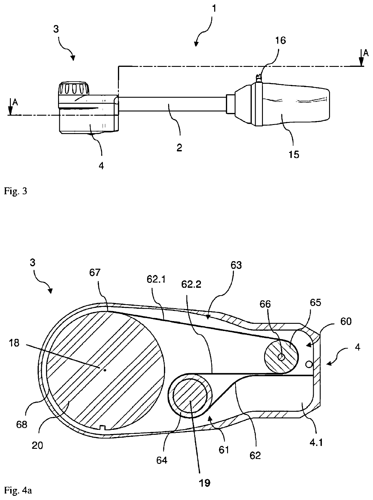
[0046]FIGS. 4a to 4c respectively show the cable storage in accordance with a first embodiment in a horizontal longitudinal section in different rotational positions of the optical unit 20, which is mounted in a rotatable manner about the axis of rotation 18, wherein FIGS. 4a and 4c show the end positions corresponding to rotation through approximately 180° and FIG. 4b shows a rotational position lying therebetween. The rotation angle of the optical unit 20 is restricted by one or more stops.
[0047]What can be seen in FIG. 4a is that the substantially cylindrically formed optical unit 20 and the cable storage 63, which comprises a section of the cable 62 and the deflections 60, 61 serving as reels, are held within the hermetically sealed housing 4, the housing lower part 4.1 of which is cut in FIG. 4a. The deflection 61 comprises a stationary cylinder 64, which is securely held in the housing 4. The stationary cylinder 64 contains an illumination unit 19, for example in the form of a...
second embodiment
[0053]a cable storage is shown in FIG. 6 in a schematic illustration. As explained in relation to the first exemplary embodiment, the cable 62, proceeding from the optical unit 20, is routed via a first deflection 60, which comprises a reel 65 rotatable about an axis of rotation 66, and a stationary second deflection 61, wherein the rotatable reel 65 is guided in a linearly displaceable manner and loaded by a spring for tensioning the cable 62 and for repositioning the reel 65. In a layer mounted thereabove, a flexible element, for example an elastically flexible wire 74, which can be wound onto the circumferential surface 68 of the optical unit 20 or wound therefrom in the opposite direction, is likewise routed over two deflections. A first deflection 75 of the wire 74 has a stationary embodiment, while a second deflection is brought about by means of a rotatable reel which is mounted in a rotatable manner on the axis of rotation 66 of the first deflection 60 of the cable; the radi...
third embodiment
[0054]a cable storage is depicted schematically in FIG. 7. Here, the cable 62, proceeding from the optical unit 20, is routed over a first rotatable reel 76 with an axis of rotation 77 and a second rotatable reel 78 with an axis of rotation 79. The first and second rotatable reels 76, 78 are mounted in a frame with the axes of rotation 77, 79 thereof, which frame is embodied as a two-armed lever 80 with an axis of rotation 81. The axes of rotation 77, 79 of the reels 76, 78 and the axis of rotation 81 of the lever 80 are substantially parallel to one another. The lever 80 is pretensioned in a clockwise direction by a spring (not depicted here). If, proceeding from the situation shown in FIG. 7, the cable is wound further onto the circumferential surface 68 by rotating the optical unit 20 counterclockwise, the lever 80 likewise rotates counterclockwise, as a result of which the length of the cable 62 held in the cable storage 63 is shortened and a cable section is provided for windin...
PUM
 Abstract
Description
Claims
Application Information
 - R&D
- Intellectual Property
- Life Sciences
- Materials
- Tech Scout
- Unparalleled Data Quality
- Higher Quality Content
- 60% Fewer Hallucinations
Browse by: Latest US Patents, China's latest patents, Technical Efficacy Thesaurus, Application Domain, Technology Topic, Popular Technical Reports.
© 2025 PatSnap. All rights reserved.Legal|Privacy policy|Modern Slavery Act Transparency Statement|Sitemap|About US| Contact US: help@patsnap.com


