Brush system for an electric motor

a brush system and electric motor technology, applied in the direction of current collectors, dynamo-electric components, cooling/ventilation arrangements, etc., can solve the problems of negative effect on the lifetime overheating of the electric motor, etc., to improve the positionability of the brush system elements, improve the cable routing, and simple and cost-effective

Active Publication Date: 2015-03-26
BROSE FAHRZEUGTEILE GMBH & CO KG HALLSTADT (DE)
View PDF2 Cites 1 Cited by
  • Summary
  • Abstract
  • Description
  • Claims
  • Application Information

AI Technical Summary

Benefits of technology

[0009]It is therefore an object of the invention to provide a brush system of the that enables simply and cost-effectively an improved cable r

Problems solved by technology

The arising heat generation can lead to overheating of the ele

Method used


Image

  • Brush system for an electric motor
  • Brush system for an electric motor
  • Brush system for an electric motor

Examples


Embodiment Construction

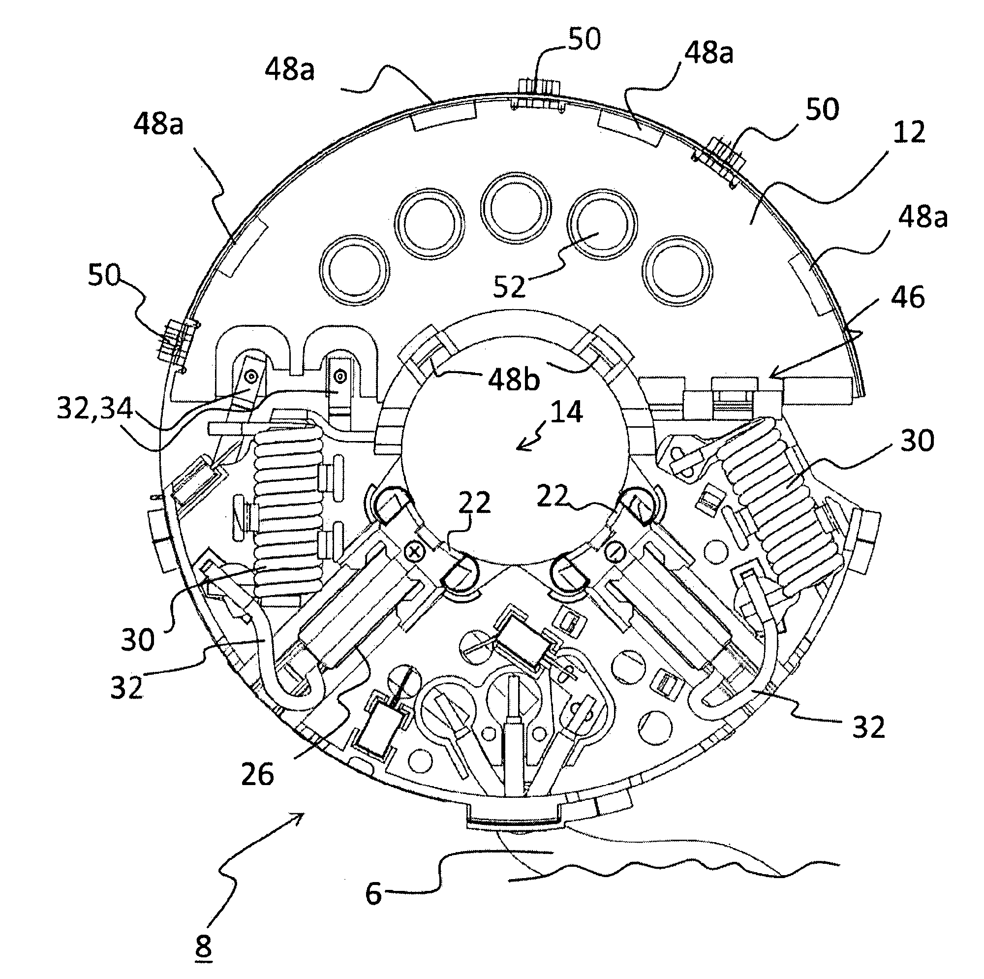
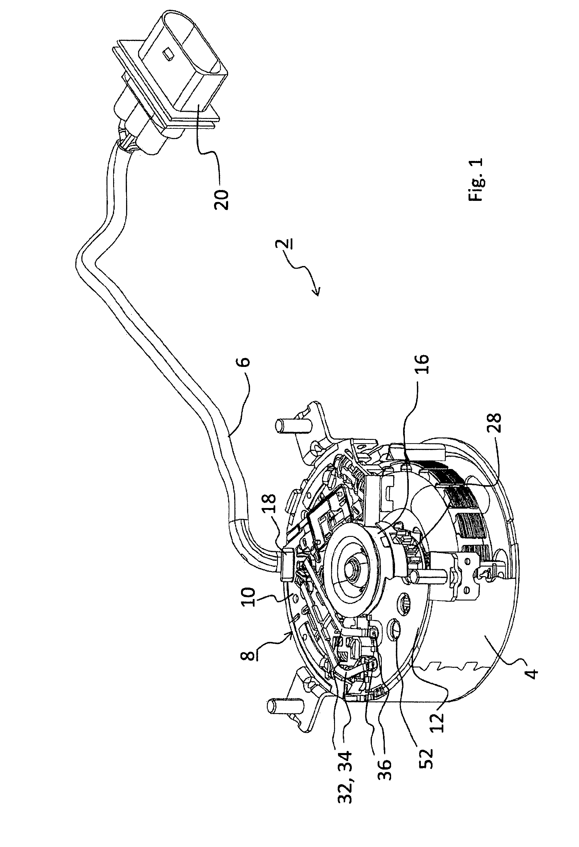
[0030]FIG. 1 shows an electromotive drive 2 with a metal motor housing 4 and with an electrical cable 6 for connecting to a conductor path and with a brush system 8. Brush system 8 is substantially circular and is formed, on the one hand, by a semi-annular support plate 10 made of an electrically nonconductive material, particularly plastic, and, on the other, by a likewise semi-annular metallic resistor housing 12. Brush system 8 has a central cut-out 14, in which in the assembled state an electric motor 16 is disposed. Brush system 8 in the assembled state is coupled to motor housing 4. Cable 6 has a plug-in connector 18 to drive 2 on the motor side and a plug type connector 20 on the conductor path side.

[0031]Brush system 8 is shown in greater detail in FIGS. 2 and 3. On the bottom side (FIG. 3) of support plate 10 produced as an injection-molded part, two carbon brushes 22 are disposed as sliding contacts on the circumference of a rotor, not shown in greater detail, of electric ...


PUM


Abstract

A brush system for an electric motor, having a substantially semiannular resistor housing into which an electric flat resistor is introduced, two resistor terminals which protrude from the resistor housing and can be coupled in an electrically conducting manner to a conductor path of the electric motor, and a substantially semi-circular support plate that includes two bus bars to electroconductively couple the conductor path to the terminals and to two brush elements. The two terminals are arranged on the same narrow side of the resistor housing.

Description

[0001]This nonprovisional application is a continuation of International Application No. PCT / EP2013 / 001540, which was filed on May 24, 2013, and which claims priority to German Patent Application No. 10 2012 010 483.9, which was filed in Germany on May 26, 2012, and which are both herein incorporated by reference.BACKGROUND OF THE INVENTION[0002]1. Field of the Invention[0003]The invention relates to a brush system for an electric motor, having a substantially semi-annular resistor housing with a flat electrical resistor introduced therein, having two resistor terminals which protrude from the resistor housing and can be coupled in an electrically conductive manner with a conductor path of the electric motor, as well as having a substantially semicircular support plate with two bus bars for the electro-conductive coupling of the conductor path to the terminals and having two brush elements, connected to interference-suppression elements, as sliding contacts for a commutator of the e...

Claims


Application Information

Patent Timeline
IPC IPC(8): H02K13/00
CPCH02K2209/00H02K13/006H02K5/148H02K11/026H02K23/66H02K11/25
Inventor SCHOELE, RAINERHARTMANN, FRANKSTOCKMANN, PETER
Owner BROSE FAHRZEUGTEILE GMBH & CO KG HALLSTADT (DE)
Why Eureka
Try Eureka