Rapid resumption of a power supply via a data link after power outage

a data link and power supply technology, applied in the field of power supply, can solve the problems of new powered devices and unnecessary delay in the and achieve the effect of fast start-up of the powered devices

Active Publication Date: 2020-01-21
SIGNIFY HLDG BV
View PDF11 Cites 0 Cited by
  • Summary
  • Abstract
  • Description
  • Claims
  • Application Information

AI Technical Summary

Benefits of technology

[0007]Therefore, it is an object of the present invention to allow for a faster start-up of the powered device upon an interruption of the power supply via a data link by an apparatus connected to the powered device. There is not always connected a new powered device to the apparatus before the beginning of each power cycle. Rather, the same powered device may be connected to the apparatus as in the preceding power cycle. This is particularly true, when a power cycle starts upon a short power outage, which may e.g. be due to a failure of the power supply of the apparatus. In such cases, the probing phase leads to an unnecessary delay in the start up of the powered device.
[0017]The power source for providing the loop current in the aforementioned embodiments may comprise a capacitor being charged by means of the power provided by the apparatus to power the powered device. The memorizing means used in these embodiments may comprise a further capacitor being discharged in response to an interruption of the current loop. Further, in one implementation, the power source corresponds to the memorizing means. In particular, the connection monitoring module may comprise a capacitor which serves as power source and as memorizing means. This reduces the complexity of the connection monitoring means.

Problems solved by technology

There is not always connected a new powered device to the apparatus before the beginning of each power cycle.
This is particularly true, when a power cycle starts upon a short power outage, which may e.g. be due to a failure of the power supply of the apparatus.
In such cases, the probing phase leads to an unnecessary delay in the start up of the powered device.

Method used


Image

  • Rapid resumption of a power supply via a data link after power outage
  • Rapid resumption of a power supply via a data link after power outage
  • Rapid resumption of a power supply via a data link after power outage

Examples


Embodiment Construction

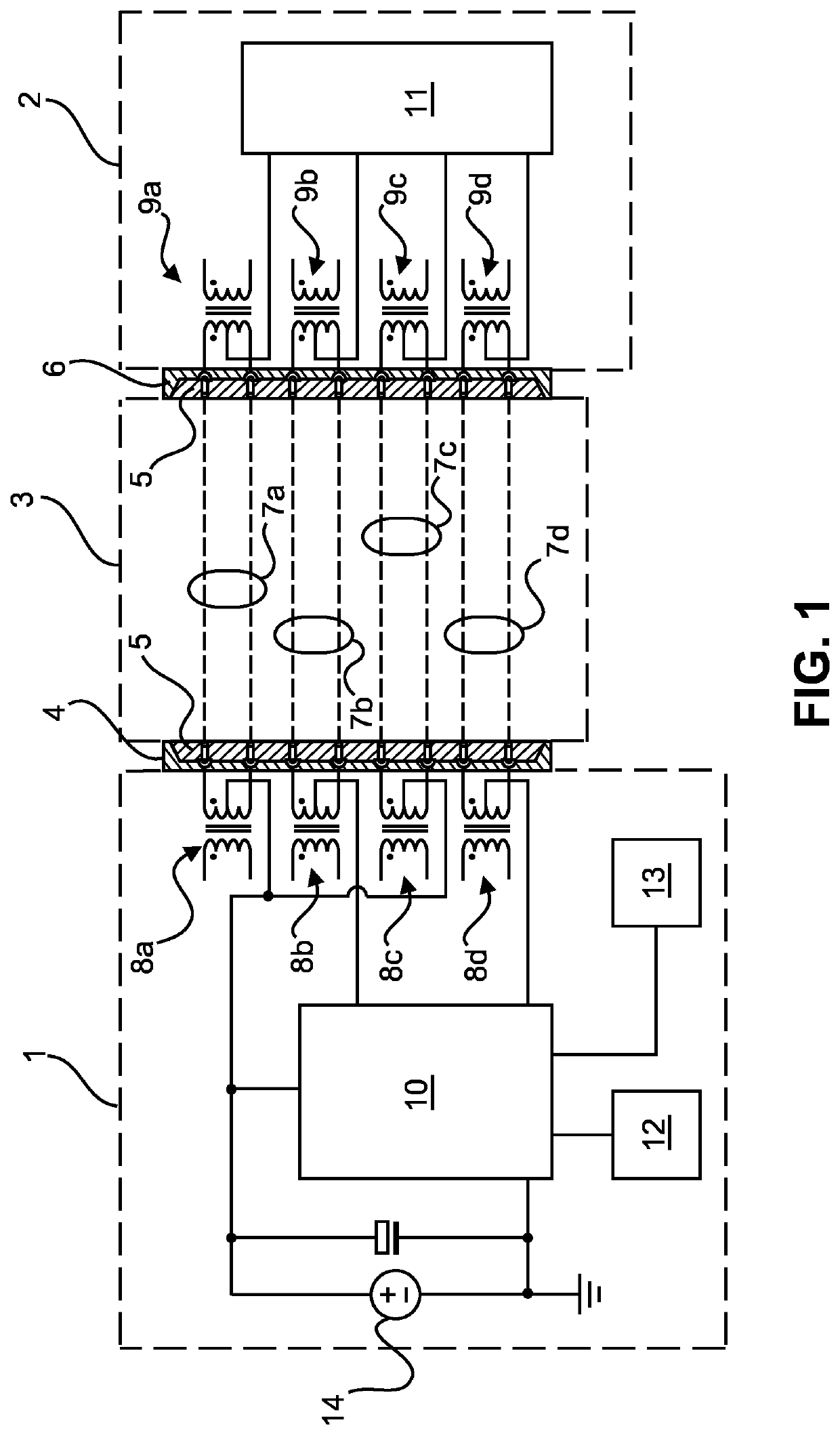
[0039]FIG. 1 schematically and exemplarily shows components of an apparatus 1 configured as a power supplying equipment (PSE) enabled to supply power to a powered device (PD) 2 over an Ethernet cable 3. In particular, components of the PSE 1 are shown, which are used for operating one Ethernet port of the PSE 1. In addition, the PSE 1 may include one or more further Ethernet ports which are equipped in an analogue way.

[0040]For receiving one of the connectors 5 of the Ethernet cable 3, the port comprises a socket 4. The powered device 2 disposes of a corresponding socket 6 for receiving the other connector 2 of the Ethernet cable 3.

[0041]In the depicted embodiment, the Ethernet cable comprises four wire pairs 7i (i=a, . . . , d) for the transmission of data from the PSE 1 to the PD 2 and vice versa. For each of the wire pairs 7i, one data transformer 8i is provided in the PSE 1 and one corresponding data transformer 9i is provided in the PD 2. One side of each of the data transforme...


PUM


Abstract

The invention relates to an apparatus (1) enabled to provide power to a powered device (2) via a wired data link (3). The apparatus (1) is configured to provide the power to the powered device (2) in accordance with a configuration determined based on at least one parameter transmitted by the powered device (2) via the wired data link (3) in a power cycle. Further, the apparatus (1) comprises a memory (12) for storing an information about the configuration and a controller (10) for controlling the apparatus (1) on the basis of the stored information to provide power in accordance with the same configuration to the powered device (12) in a subsequent power cycle after a power outage. Moreover, the invention relates to a method for operating the apparatus (1).

Description

CROSS-REFERENCE TO PRIOR APPLICATIONS[0001]This application is the U.S. National Phase application under 35 U.S.C. § 371 of International Application No. PCT / EP2016 / 054056, filed on Feb. 26, 2016, which claims the benefit of European Patent Application No. 15158625.2, filed on Mar. 11, 2015. These applications are hereby incorporated by reference herein.FIELD OF THE INVENTION[0002]The invention relates to a power supply of a powered device via wired data link. More specifically, the invention is related to an apparatus enabled to provide power to a powered device via a wired data link for connecting the apparatus and the powered device. Moreover, the invention is related to a method for operating the apparatus and to a computer program for causing a processing unit of the apparatus to carry out the method.BACKGROUND OF THE INVENTION[0003]In order to facilitate the power supply of electrical devices exchanging data with further equipment, mechanisms have been developed that allow for...

Claims


Application Information

Patent Timeline
Patent Type & Authority Patents(United States)
IPC IPC(8): G06F1/30G06F1/24G06F1/28G06F1/3206
CPCG06F1/305G06F1/28G06F1/24G06F1/3206H04L12/10G06F1/30
Inventor WENDT, MATTHIASWOUDENBERG, ROBERT
Owner SIGNIFY HLDG BV
Why Eureka
Try Eureka