Insulation displacement connector

a technology of displacement connector and connector, which is applied in the direction of contact members penetrating/cutting insulation/cable strands, electrical equipment, and unstripped conductor connection apparatus, etc., can solve the problem of difficult to determine if the branch wire is properly positioned for forming an electrical connection, and achieve the effect of reliably splicing a branch wir

Active Publication Date: 2020-01-21
THE PATENT STORE
View PDF34 Cites 11 Cited by
  • Summary
  • Abstract
  • Description
  • Claims
  • Application Information

AI Technical Summary

Benefits of technology

[0006]An insulation displacement connector using a blind connection for reliably splicing a branch wire to a main wire without cutting the main wire. The connector having an insulation filled cover with a foldable lid attached thereto with the lid carrying a sleeve having a side opening for latterly inserting and axially positioning the connector along an uncut main wire therein and a cylindrical opening extending therethrough for axially inserting a cantilevered end of a branch wire through the cylindrical opening in the sleeve and into engagement with a wire stop located in axial alignment with the cylindrical open

Problems solved by technology

One of difficulties with forming a branch attachment to a main wire is that one needs to ensure that the branch electrical wires are properly positioned in the wire connector before the electrical

Method used


Image

  • Insulation displacement connector
  • Insulation displacement connector
  • Insulation displacement connector

Examples


Embodiment Construction

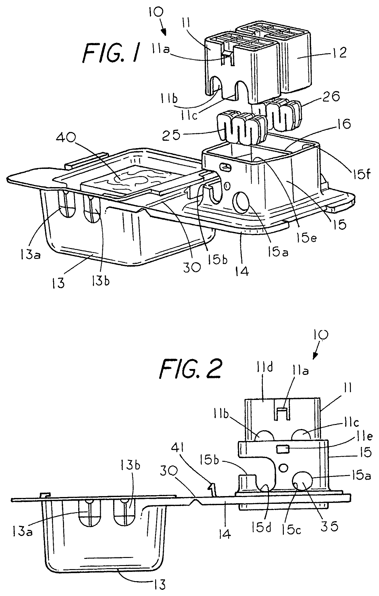
[0020]FIG. 1 is a perspective exploded view of an insulation displacement connector 10 showing a sealant 40 located in a cover 13 that is connected to a lid 14 through a living hinge 30. Located on lid 14 is a rectangular shaped sleeve 15 having a first rectangular shaped piston compartment 15e and a second rectangular shaped piston compartment 15f with a divider 16 extending therebetween. A first edge blade connector 25 is shown located above compartment 15e and below a slideable piston 11 having a chamber 11b for mounting the blunt edge blade connector 25 therein. A second identical blunt edge blade connector 26 is shown located above compartment 15d and below a slideable piston 12 having an identical chamber therein for mounting the blunt edge blade connector 26 therein with each having blunt edge blades therein. In this example, piston 12 and piston 11 are independently slideable into an electrical connection with the wires therein. The blunt edge blade connectors 25 and 26 are ...


PUM


Abstract

A method and apparatus for forming a blind connection between a first wire and a second wire where each of the wires are inserted into a sleeve with the first wire laterally inserted into the sleeve for positioning along the first wire and the second wire axially inserted through the sleeve and into engagement with a stop located outside the sleeve to ensure that the second wire is properly positioned in the sleeve before an unseen electrical connection is formed between the first wire and the second wire.

Description

BACKGROUND OF THE INVENTION[0001]Insulation displacement connectors are well known in the art and typically comprise a pair of cantilevered spaced apart blade members each having an internal edge for penetrating through an outer insulation wire cover to bring the internal edges into electrical contact with the electrical wire. The insulation displacement connectors, which are often referred to as IDC connectors, allow one to quickly form an electrical connection between an insulation covered electrical wire and the blade members of the IDC connector without having to manually remove the insulation covering on the wire. The spacing of the blunt edges of the blade from each other are sized so that when an electrical wire with an insulation covering is forced between the blunt edge blades the blunt edged blades penetrate through the soft insulation covering to bring the blunt edge of the blades into electrical contact with the electrical wire without damaging the electrical wire. Typic...

Claims


Application Information

Patent Timeline
IPC IPC(8): H01R4/24H01R4/2433H01R43/01H01R4/70
CPCH01R4/2433H01R43/01H01R4/70
Inventor KING, JR., L. HERBERTKEEVAN, JAMESHINER, WILLIAM
Owner THE PATENT STORE
Why Eureka
Try Eureka