Hermetic compressor and refrigeration device

a compressor and refrigeration device technology, applied in the direction of positive displacement liquid engines, pumping, lighting and heating apparatus, etc., can solve the problems of unsatisfactory noise control effect, high noise, and high noise generation, and achieve the effect of reducing noise, reducing noise, and reducing vibration of hermetic containers

Active Publication Date: 2020-01-28
PANASONIC APPLIANCES REFRIGERATION DEVICES SINGAPORE
View PDF16 Cites 0 Cited by
  • Summary
  • Abstract
  • Description
  • Claims
  • Application Information

AI Technical Summary

Benefits of technology

[0016]The present invention solves the above conventional problems. The present invention enables a dynamic vibration absorbing effect to be exerted without being affected by an external factor such as a state in which a hermetic compressor is mounted while enabling low cost by preventing a parts count, mass, and volume from increasing. Moreover, the present invention can provide a hermetic compressor that exerts a stable noise control effect while avoiding an insufficient contact friction damping effect of a vibration damping plate.
[0018]Thus, a dynamic vibration absorbing effect is exerted only with two components, that is, legs of the hermetic container and the vibration damping member. Consequently, noise resulting from vibration of the hermetic container can be reduced. Moreover, since this effect is exerted only with the two components, that is, the hermetic container and the vibration damping member, the dynamic vibration absorbing effect is reliably exerted without being affected by the state in which the hermetic container is mounted to an appliance.
[0019]Thus, the hermetic compressor provided by the present invention can reduce the noise irrespective of installation variations and is low-cost and highly reliable.

Problems solved by technology

At the same time, harsh harmonic noise in a human audible range, such as suction / discharge valve tapping noise of the compression mechanism, is transmitted to the hermetic container through a solid contact portion for excitation, thereby producing noise.
Consequently, noise levels particularly tend to increase in the above frequency band.
The hermetic compressor of the rotary type or the like has a noise problem associated with a fundamental wave having 50 Hz / 60 Hz pressure pulsation.
On the other hand, the hermetic compressor of the reciprocating type problematically produces harmonic noise in a band of resonance frequencies (2 kHz to 8 kHz) that is attributed to the natural frequency of the hermetic container, and the resonance frequencies in this band are higher by an order of magnitude or more than the frequency of the problematic noise of the hermetic compressor of the rotary type or the like.
This problem is peculiar to the reciprocating type.
However, there are cases where a satisfactory noise control effect is not obtained when the hermetic compressor is mounted to an appliance, such as a refrigerator, in parts that change in rigidity.
Thus, there is a problem of lack of reliability.
As a result, a satisfactory dynamic vibration damping effect cannot be exerted, so that the hermetic compressor cannot achieve noise reduction or has a small noise reducing effect, thus lacking reliability.
Accordingly, the hermetic compressor has an increased parts count and increased weight, thus becoming high-cost and having an increased size.
For this reason, there are cases of such an adverse effect that capacity inside the appliance such as the refrigerator reduces as the appliance has increased mounting capacity.
However, there are cases where a satisfactory noise control effect is not obtained.
Thus, lack of reliability is problematic.
Thus, this hermetic compressor lacks reliability.

Method used


Image

  • Hermetic compressor and refrigeration device
  • Hermetic compressor and refrigeration device
  • Hermetic compressor and refrigeration device

Examples


first exemplary embodiment

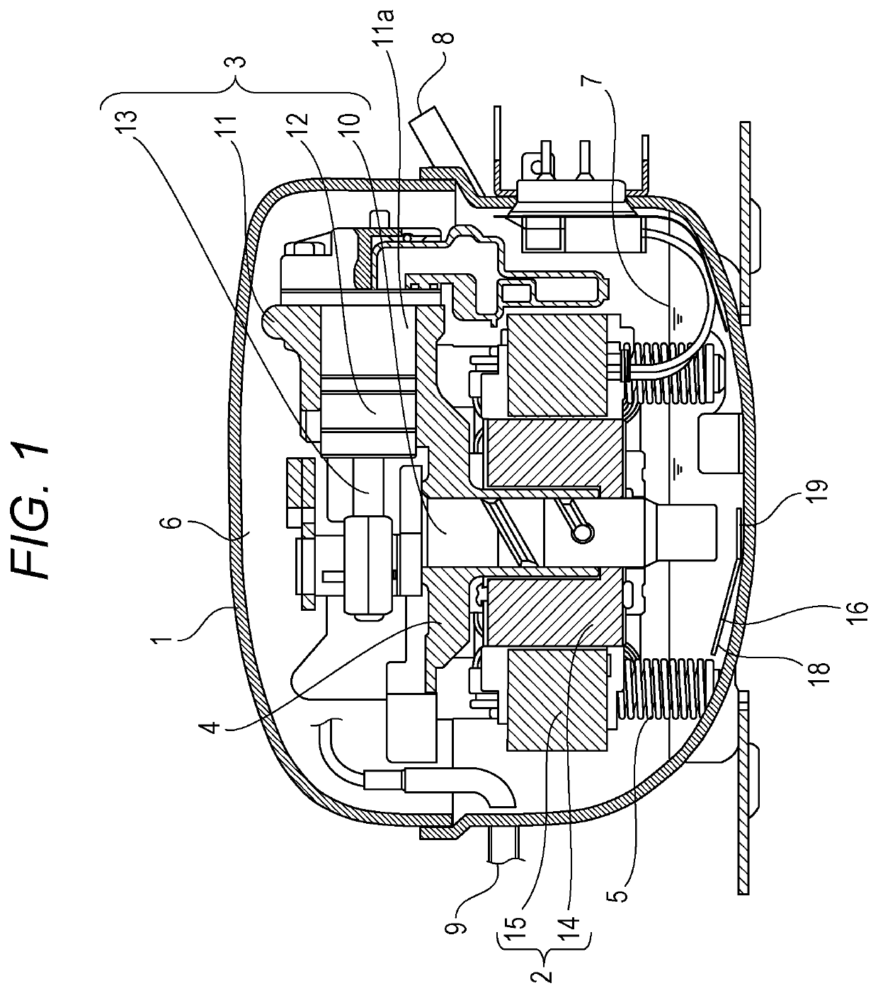
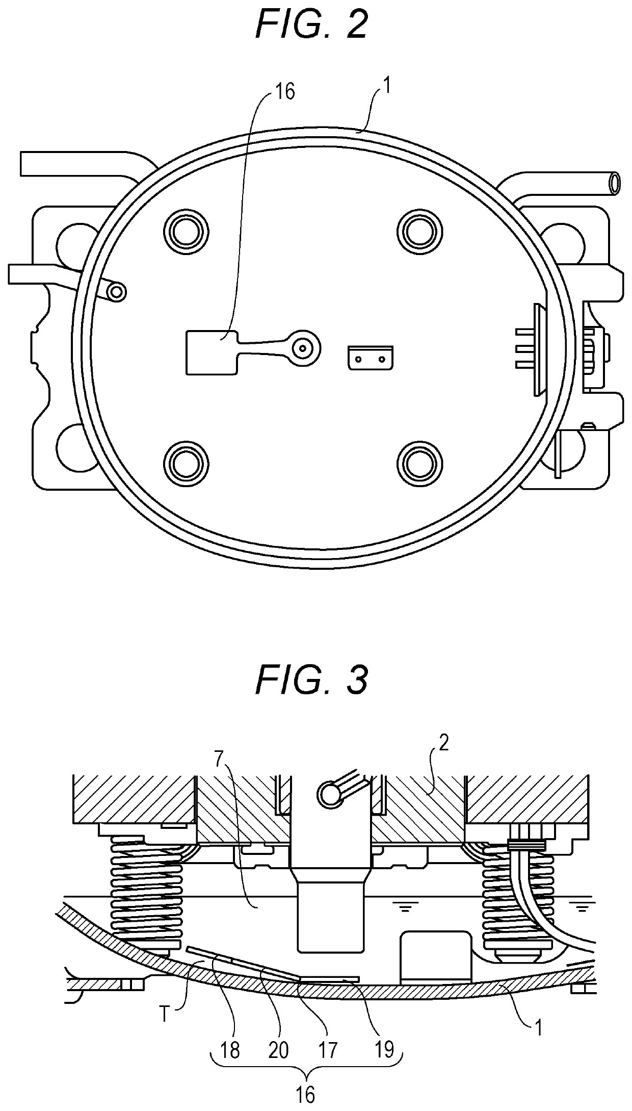
[0054]FIG. 1 is a sectional view of a hermetic compressor according to the first exemplary embodiment of the present invention. FIG. 2 is a plan view illustrating an inner bottom surface of a hermetic container of the hermetic compressor. FIG. 3 is an enlarged sectional view of an essential part of the hermetic compressor.

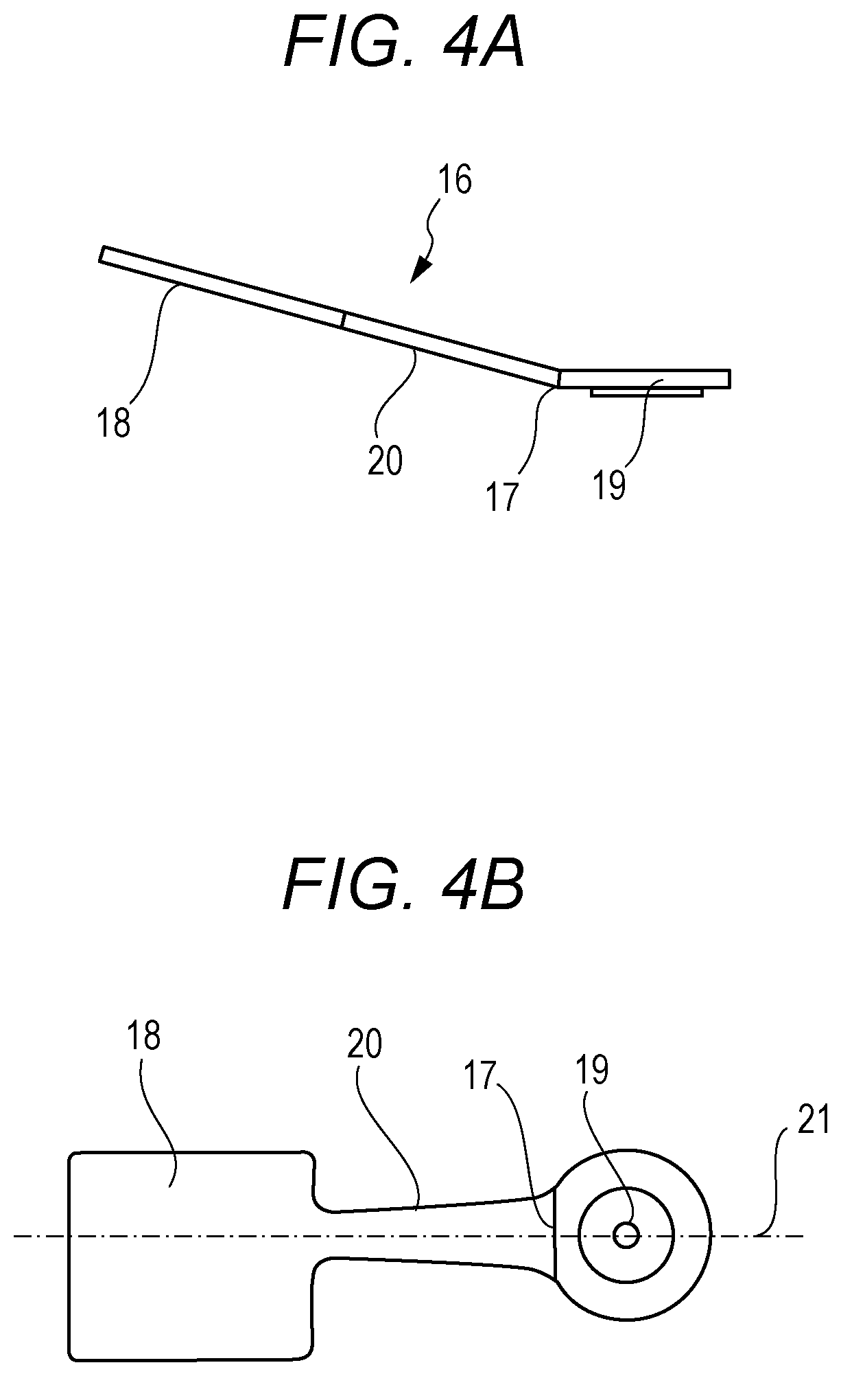
[0055]FIG. 4A is a side view of a vibration damping member fixed to the hermetic container of the hermetic compressor. FIG. 4B is a plan view of the vibration damping member fixed to the hermetic container of the hermetic compressor. FIG. 5A illustrates a vibrational state of the hermetic compressor. FIG. 5B illustrates a noise condition of the hermetic compressor.

[0056]FIGS. 6A, 6B, 6C, 6D, 6E, 6F, 6G, 6H, 6I, and 6J each illustrate other examples of the vibration damping member fixed to the hermetic container of the hermetic compressor. FIGS. 7A, 7B, 7C, and 7D are sectional views each schematically illustrating an example of a fixed position of each vibration da...

second exemplary embodiment

[0124]FIG. 8 is an enlarged sectional view of an essential part of a hermetic compressor according to the second exemplary embodiment of the present invention. FIG. 9 is a plan view illustrating an inner bottom surface of hermetic container 1 of the hermetic compressor.

[0125]FIG. 10A is a side view of a vibration damping member of the hermetic compressor. FIG. 10B is a plan view of the vibration damping member of the hermetic compressor. FIG. 11A illustrates a vibrational state of the hermetic container of the hermetic compressor. FIG. 11B illustrates a noise condition of the hermetic compressor.

[0126]FIG. 12A illustrates another first example of the vibration damping member of the hermetic compressor. FIG. 12B illustrates another second example of the vibration damping member of the hermetic compressor. FIG. 12C illustrates another third example of the vibration damping member of the hermetic compressor.

[0127]It is to be noted that except for the vibration damping member, elements ...

third exemplary embodiment

[0154]FIG. 13 is a schematic view illustrating a structure of a refrigeration device according to the third exemplary embodiment of the present invention. The refrigeration device is mounted with the hermetic compressor described in the first or second exemplary embodiment in a refrigerant circuit of the refrigeration device. A summary of a basic structure of the refrigeration device is provided.

[0155]In FIG. 13, the refrigeration device includes main body 51, partition wall 54, and refrigerant circuit 55. Main body 51 is formed of a thermally insulated housing having an opening provided with a door. Partition wall 54 divides an interior of main body 51 into storage space 52 for articles and machine chamber 53. Refrigerant circuit 55 provides cooling for storage space 52.

[0156]Refrigerant circuit 55 has compressor 56, radiator 57, decompression device 58, and heat absorber 59 that are connected in a loop by piping. Compressor 56 is the hermetic compressor described in the first or s...


PUM


Abstract

A hermetic compressor includes, inside hermetic container (1), electric motor element (2), compression element (3) driven by electric motor element (2), and lubricating oil (7) for lubricating compression element (3). The hermetic compressor further includes vibration damping member (16) having one part fixed to hermetic container (1) and another part being free end part (18). Structurally, a natural frequency of vibration damping member (16) is in substantial conformity with a natural frequency of hermetic container (1).

Description

TECHNICAL FIELD[0001]The present invention relates to a hermetic compressor and a refrigeration device using the same, such as a refrigerator or a showcase. The present invention more particularly relates to a noise control structure of the hermetic compressor.BACKGROUND ART[0002]A hermetic compressor is generally formed to have, for example, a compression mechanism of a reciprocating type, a rotary type or a scroll type inside a hermetic container. The compression mechanism sucks in, compresses and discharges a refrigerant. The suction, compression and discharge of the refrigerant cause pulsation, so that vibration having a low frequency of 50 / 60 Hz attributed to operating rotational speed and noise are transmitted via the refrigerant and lubricating oil inside the hermetic container. At the same time, harsh harmonic noise in a human audible range, such as suction / discharge valve tapping noise of the compression mechanism, is transmitted to the hermetic container through a solid co...

Claims


Application Information

Patent Timeline
Patent Type & Authority Patents(United States)
IPC IPC(8): F04B39/00F04B39/02F25B31/02F04B39/12F04B49/20F25B1/02F04B35/04
CPCF04B35/04F04B49/20F25B31/023F04B39/0044F04B39/02F25B1/02F25B2500/13F25B2500/12F04B39/0027F04B39/023F04B39/121
Inventor KOBAYASHI, MASANORIYOKOTA, KAZUHIROIDE, TERUMASAKINJO, KENJI
Owner PANASONIC APPLIANCES REFRIGERATION DEVICES SINGAPORE
Why Eureka
Try Eureka