Brake calipers

a technology of brake calipers and opposed pistons, which is applied in the direction of axially engaging brakes, braking elements, actuators, etc., can solve the problem that the opposing pistons of the opposing piston caliper cannot be used to provide the effect of reducing the friction of the axial axis of the axis, and reducing the friction of the axial axis

Active Publication Date: 2020-01-28
LIBERTY VEHICLE TECH LTD
View PDF24 Cites 1 Cited by
  • Summary
  • Abstract
  • Description
  • Claims
  • Application Information

AI Technical Summary

Benefits of technology

[0009]The caliper of the present invention allows both the service braking force and the park braking force to be applied to the brake disc via the braking members. By providing the service braking force and park braking force via the same set of braking members, the brake caliper of the present invention can be made smaller and lighter than the dual braking systems of the prior art. A body of the brake caliper of the present invention can advantageously be made to fit within a small footprint, for example, within the same or similar profile as an existing fixed service brake caliper and removes the need for a secondary caliper to apply a park braking force. The fixed brake caliper with integrated park brake of the present invention is therefore more compact, lighter, less complex to manufacture and therefore offers a technical advantage over the prior art. The caliper of the present invention may also allow simplification of the caliper mounting to the vehicle (compared to using a secondary caliper for example).
[0036]Optionally, the engagement member may comprise a plate or one or more finger members arranged to distribute the park braking force. This allows the force to be effectively distributed over the second braking member surface. Optionally, the finger members may be arranged to surround at least part of the second piston to allow the service braking force and the park braking force to be applied through points close together on the surface of the second braking member.

Problems solved by technology

The opposed pistons of an opposed piston caliper cannot however also be used to provide a parking brake, as a mechanism is required that maintains a braking force by direct mechanical means even when the service braking system is not active.

Method used


Image

  • Brake calipers
  • Brake calipers
  • Brake calipers

Examples


Embodiment Construction

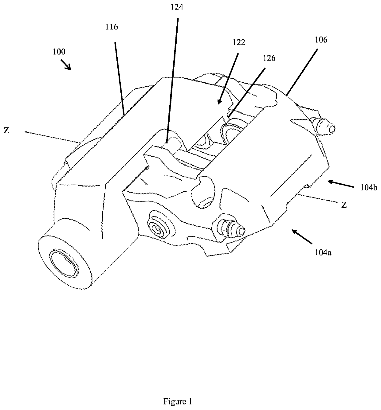
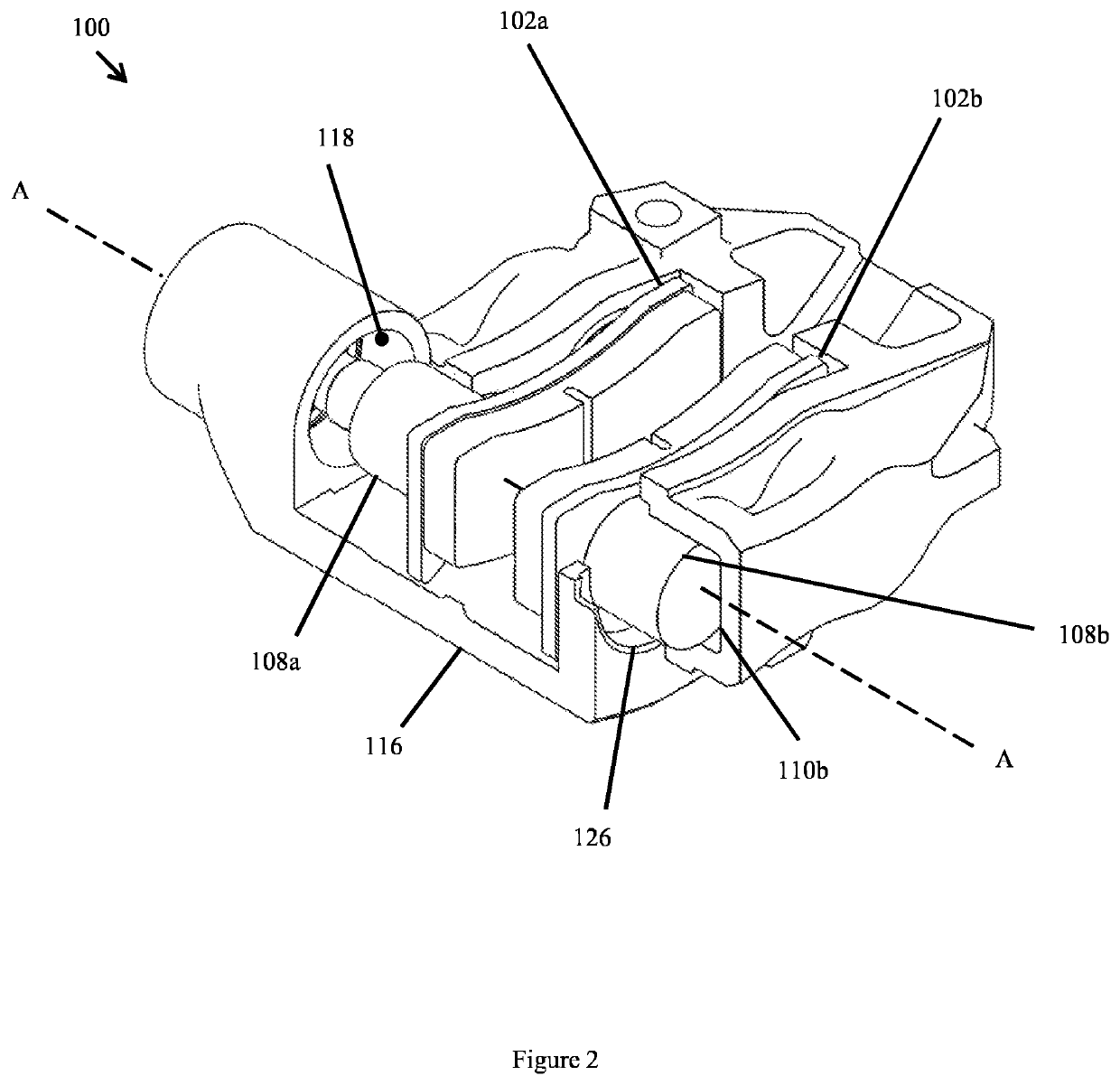
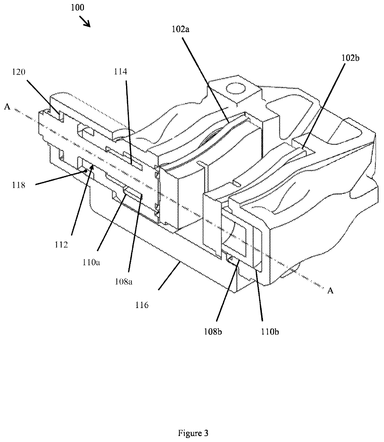
[0050]An embodiment of a brake caliper 100 according to the present invention is shown in FIGS. 1, 2, 3 and 4. The brake caliper 100 receives at least two opposed braking members comprising a first braking member 102a and a second braking member 102b, each movable to apply a braking force to a brake disc (not shown in the figures) disposed between the braking members 102a, 102b. The caliper shown in FIG. 1 is however only one such example, in other embodiments any other number of additional braking members may be provided as will be described later. In some embodiments, the braking members 102a, 102b comprise a brake pad arranged to generate a friction force when forced against the brake disc, thereby slowing or preventing the rotation of the brake disc. In other embodiments, the braking members may comprise a support member arranged to receive a brake pad as is known in the art. The first braking member 102a and the second braking member may be arranged such that their centres are ...


PUM


Abstract

A brake caliper (100) with first and second parts (104a, 104b) between which is received a pair of braking members (102a, 102b). The caliper (100) includes a service brake mechanism having at least two piston and cylinder assemblies (108a, 110a and 108b, 110b) forming an opposed piston mechanism for forcing each of the braking members (102a, 102b) towards a brake disc to apply a service braking force thereto. The caliper (100) also includes a park brake mechanism including an actuator mechanism (112) for applying a driving force to a first opposed braking member (102a) towards the brake disc and a force transmitting member (116) for transmitting the driving force to a second opposed braking member (102b). The force transmitting member (116) is supported by a sliding connection between the force transmitting member (116) and an outer surface of a first cylinder (110a) and a slidable connection between the force transmitting member (116) and a connecting member that spans the first and second parts of the brake caliper (100).

Description

BACKGROUND[0001]1. Technical Field[0002]The present invention relates to a brake caliper, a braking apparatus and a vehicle. The present invention may in particular relate to a brake caliper for applying a braking force to a brake disc of a vehicle.[0003]2. Related Art[0004]As is known in the art, many vehicle braking systems are required to provide two separate braking forces a service braking force and a park braking force. The service braking force is provided to slow the speed of the vehicle and bring it to a stop when required. The park braking force is required to keep the vehicle stationary when it is at rest e. g. when it is parked.[0005]In order to provide a braking force acting towards each side of the brake disc (such that the brake pads grip the brake disc from both sides) it is known to use two basic types of caliper, moving (often referred to as sliding or floating) brake calipers or fixed brake calipers (often referred to as opposed piston). A moving caliper is arrang...

Claims


Application Information

Patent Timeline
Patent Type & Authority Patents(United States)
IPC IPC(8): F16D65/14F16D55/228F16D65/095F16D65/18F16D55/00F16D121/04F16D121/24F16D125/36F16D125/40F16D125/60F16D125/64
CPCF16D55/228F16D65/18F16D65/095F16D2125/64F16D2125/36F16D2121/04F16D2055/0066F16D2055/0091F16D2125/40F16D2125/60F16D2121/24F16D2125/28
Inventor THOMAS, PHILIPBLACKWELL, ANTHONYMUTCH-MATHIESON, DANIELPHILIPS, ANTHONYRIPPIN, LAURIESHEPHERD, BENJAMIN
Owner LIBERTY VEHICLE TECH LTD
Why Eureka
Try Eureka