Valve manifold serially mounted to a distributed control system assembly

a distributed control system and valve manifold technology, applied in the field of electric bus systems, can solve the problems of high cost and labor intensity, unsatisfactory complexity of sensors, and high connection methods

Active Publication Date: 2020-02-04
ASCO LP
View PDF14 Cites 2 Cited by
  • Summary
  • Abstract
  • Description
  • Claims
  • Application Information

AI Technical Summary

Problems solved by technology

The use of two networks to coordinate the valves and sensors adds a level of undesirable complexity.
This connection method, however, is expensive and labor intensive by the need to wire a separate CHARM I / O module with its own microprocessor to each solenoid valve of each valve station on the manifold.

Method used


Image

  • Valve manifold serially mounted to a distributed control system assembly
  • Valve manifold serially mounted to a distributed control system assembly
  • Valve manifold serially mounted to a distributed control system assembly

Examples


Embodiment Construction

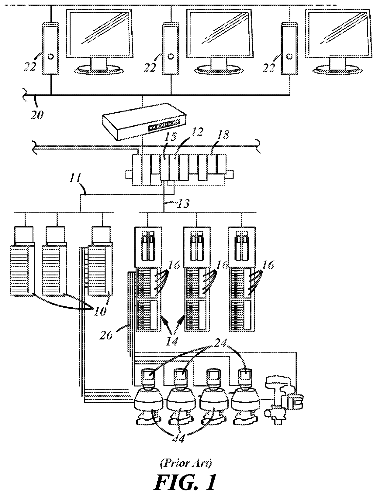
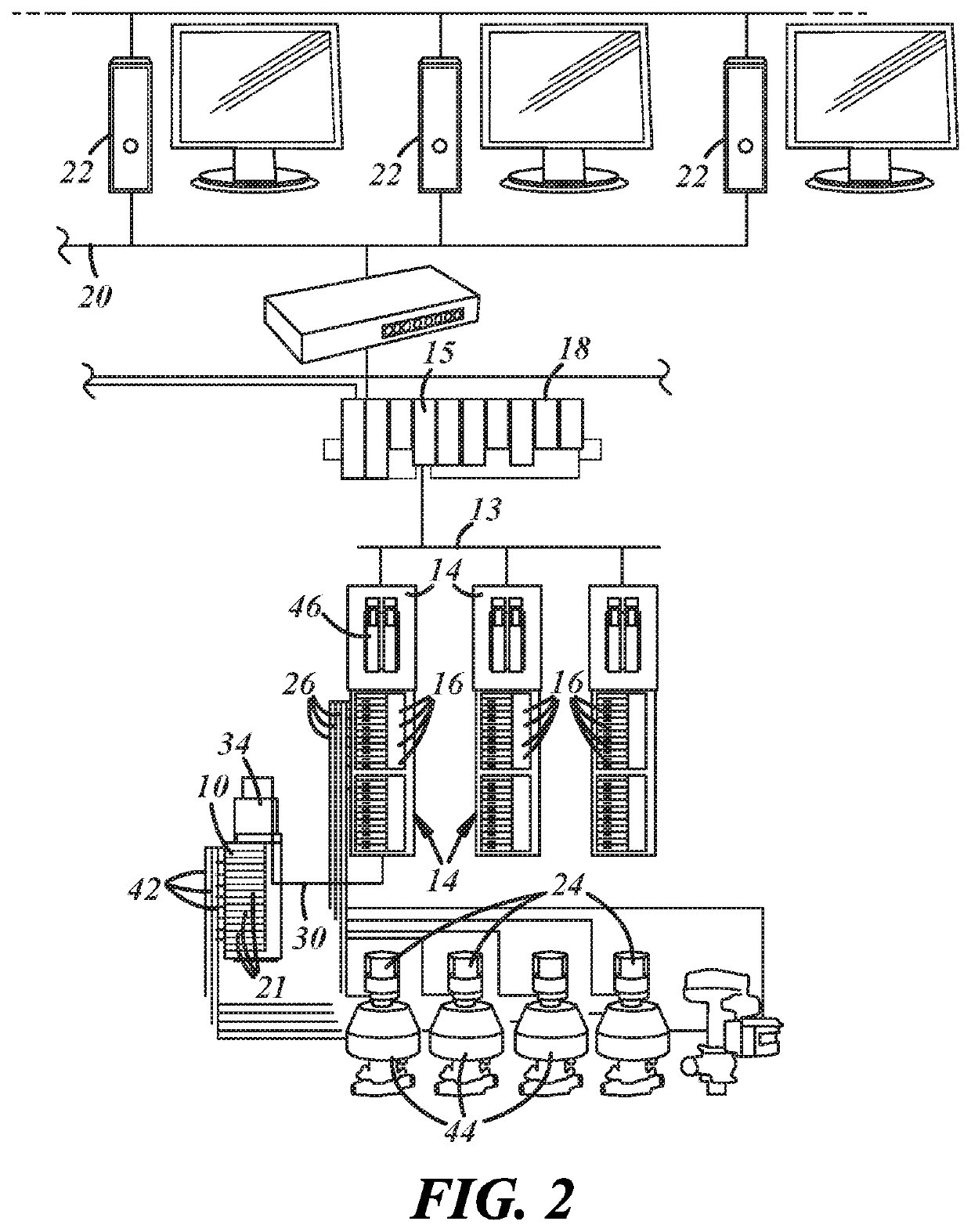
[0024]Referring now to FIG. 2, a control network 20 has a plurality of work stations 22 connected to a DCS 18. The DCS may be a commercially available DELTAV™ system from Emerson Process Management. The DCS 18 is in turn connected through its network 13 to one or more I / O banks 14 containing individual Input / Output modules 16. A suitable bank of I / Os may be the commercially available CHARM™ I / O bank from Emerson Process Management. These I / O banks 14 may be remotely positioned from the DCS 18.

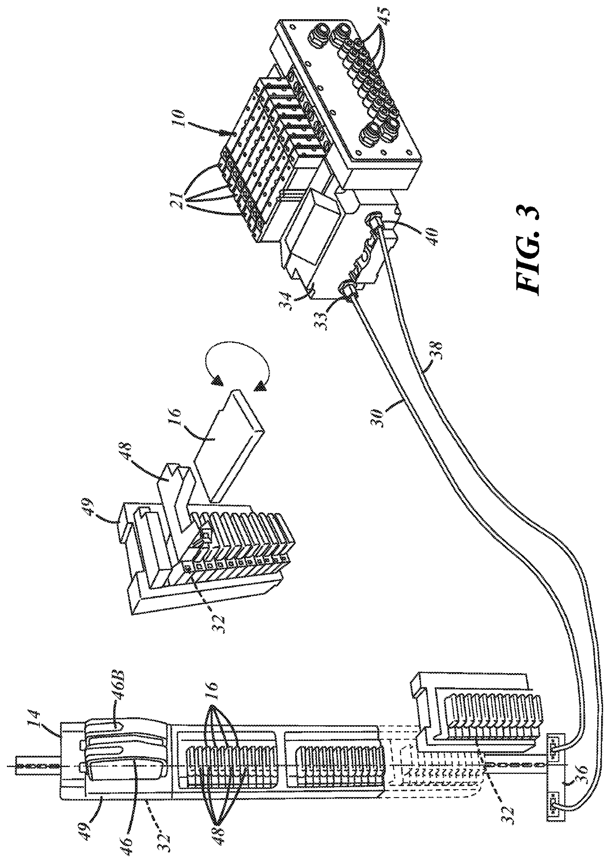
[0025]Many of the individual I / O modules 16 in the bank may be connected to field sensors 24 through cables 26 for receiving information from the field sensors 24. In addition, a valve manifold 10 may also be connected to the I / O bank 14. Preferably, as illustrated in FIG. 3, the connection is made by extending a cable 30 that integrates both power and communication from a backplane 32 of the I / O bank 14 to the communication fitting 33 of a communication module 34 of the valve manifold 10. More...


PUM


Abstract

A control system has an I / O bank with a communication module controlling a plurality of Input / Output modules operably connected to its communication backplane and a valve manifold having a communication module serially connected to the backplane of the I / O bank. The I / O bank with a plurality of Input / Output modules is constructed to be connected to a plurality of field sensors or loads. The valve manifold with a plurality of solenoid valves is constructed to be pneumatically connected to a plurality of field devices.

Description

TECHNICAL FIELD[0001]The field of this invention relates to an electrical bus system that has a solenoid valve manifold that is serially connected to a distributed control system via a distribution I / O system.BACKGROUND OF THE DISCLOSURE[0002]Industrial automation uses many control devices. One useful control device is a solenoid valve manifold, often simply referred to as a valve manifold, that houses a plurality of electrically actuated solenoid valves. The solenoid valves control the direction of hydraulic or pneumatic flow for actuating other downstream field devices, for example process valves. These valve manifolds have communication modules that often mount adjacent the solenoid valve stations, and connect to various fieldbus networks.[0003]These fieldbus networks have become commonplace in automation control. The fieldbus network provides remote control over the valve stations. Typical fieldbus networks may use EtherNet / IP™, FIPIO™, Interbus-S™, ControlNet™ DeviceNet™ or oth...

Claims


Application Information

Patent Timeline
Patent Type & Authority Patents(United States)
IPC IPC(8): H01R9/22H05K7/14
CPCH05K7/1467H05K7/1479G05B19/054G05B19/0423G05B19/44
Inventor DE CAROLIS, ENRICOESKEW, JOHN F.WELLS, GREGORY A.
Owner ASCO LP
Why Eureka
Try Eureka