

Spinal fusion implant for oblique insertion
a spinal fusion and implant technology, applied in the field of spinal fusion implants for oblique insertion, can solve problems such as poor fixation
Active Publication Date: 2020-02-11
CAMBER SPINE TECH
View PDF31 Cites 7 Cited by
- Summary
- Abstract
- Description
- Claims
- Application Information
AI Technical Summary
Benefits of technology
The implants in this patent have a hole in the middle that allows bone material to grow and fuse with the implant. The hole can be separated into multiple sections using dividers. This design helps to promote bone growth and makes the implant more secure in the body.
Problems solved by technology
A challenge in spinal fusion is achieving a proper fit between an implant and the adjacent vertebrae.
If an implant is not flush against the concave vertebral plates, then it can loosen and move out of place, resulting in poor fixation.
Method used
View moreImage
Smart ImageViewing Examples

Examples
example
Example 1. Correction of Lordotic Angle in Patients Using Implants Described Above
[0211]Three patients with lumbar pathology received the offset bi-convex implant. They were operated on to restore the natural lumbar lordosis and disc heights. The offset bi-convex implants were positioned in between two adjacent vertebrae at the site of pathology according to the method described above. Patient 1 had a pre-operative lordotic angle measurement from L4-S1 of 11°, which was corrected and measured 16° following the operation. Patients 2 and 3 had operative lordotic angle measurements from L4-L5 of 5°, which were corrected and measured 7° following the operation.
Login to View More PUM
 Abstract
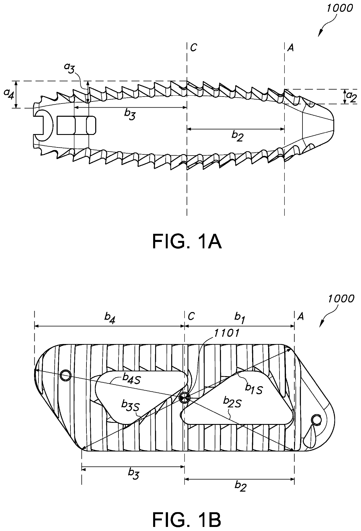
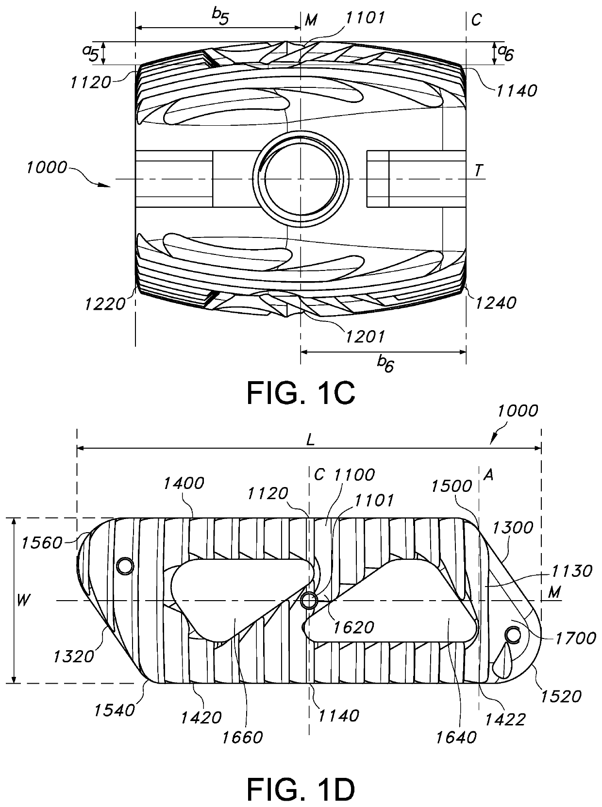
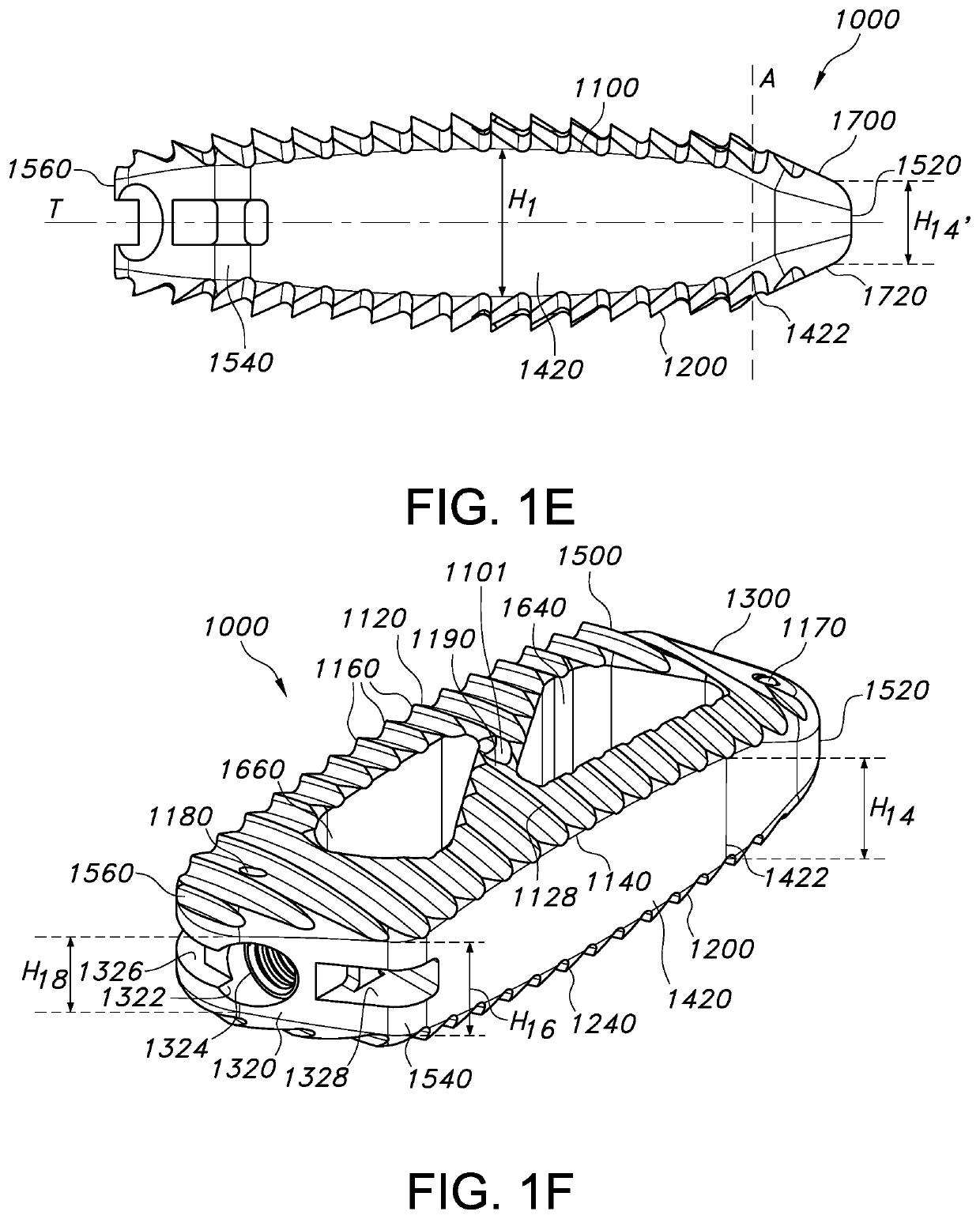
Intervertebral spinal fusion implants for interbody fusion of the anterior column of the spine are described. The implants have a substantially bi-convex or a substantially offset bi-convex shape. The implants are placed through a transforaminal or posterior approach at an oblique insertion angle. The implants have an outermost point on the superior convex surface and an outermost point on the inferior convex surface and four edges of differing heights. The outermost superior and inferior points of the implants are connected with the four edges with convex surfaces of different curvatures. The curvatures of the convex surfaces of the implants are designed to match the curvatures of concave vertebral surfaces when the implants are inserted at an oblique insertion angle.
Description
CROSS-REFERENCE TO RELATED APPLICATION[0001]The present application claims priority to U.S. Application No. 62 / 151,947, filed on Apr. 23, 2015, by Jeffrey R. McConnell and William Duffield, the disclosure of which is incorporated herein by reference in its entirety.FIELD OF THE INVENTION[0002]This invention relates to implantable devices and methods for use in spinal surgery.BACKGROUND OF THE INVENTION[0003]The standard treatment for chronic pain related to damaged or displaced discs is lumbar spinal fusion. In preparation for the spinal fusion, a damaged disc is removed entirely. A device, such as an intervertebral cage or implant, can be placed between the vertebrae to restore proper spine alignment and disc height. This also reduces, if not eliminates, neural impingement commonly associated with a damaged or diseased disc.[0004]Minimally invasive methods of performing spinal fusion have gained popularity in recent years due to the many benefits of the procedure, which include dim...
Claims
Login to View More Application Information
Patent Timeline
 Patent Type & AuthorityPatents(United States)
IPC IPC(8): A61F2/44
CPCA61F2/4455A61F2230/0082A61F2002/30593A61F2/447A61F2/4611A61F2/4684A61F2002/3008A61F2002/30151A61F2002/30156A61F2002/30616A61F2002/30797A61F2002/30828A61F2002/30904A61F2002/448
InventorMCCONNELL, JEFFREY R.DUFFIELD, WILLIAM
OwnerCAMBER SPINE TECH