
Optical communication module and optical modulator used therein

a technology of optical communication module and optical modulator, which is applied in the direction of optical elements, electromagnetic transceivers, instruments, etc., can solve problems such as performance degradation of optical communication modules, and achieve the effect of miniaturizing the optical communication module and suppressing the propagation loss of high-frequency signals

Active Publication Date: 2020-02-11
SUMITOMO OSAKA CEMENT CO LTD
View PDF33 Cites 0 Cited by
  • Summary
  • Abstract
  • Description
  • Claims
  • Application Information

AI Technical Summary

Benefits of technology

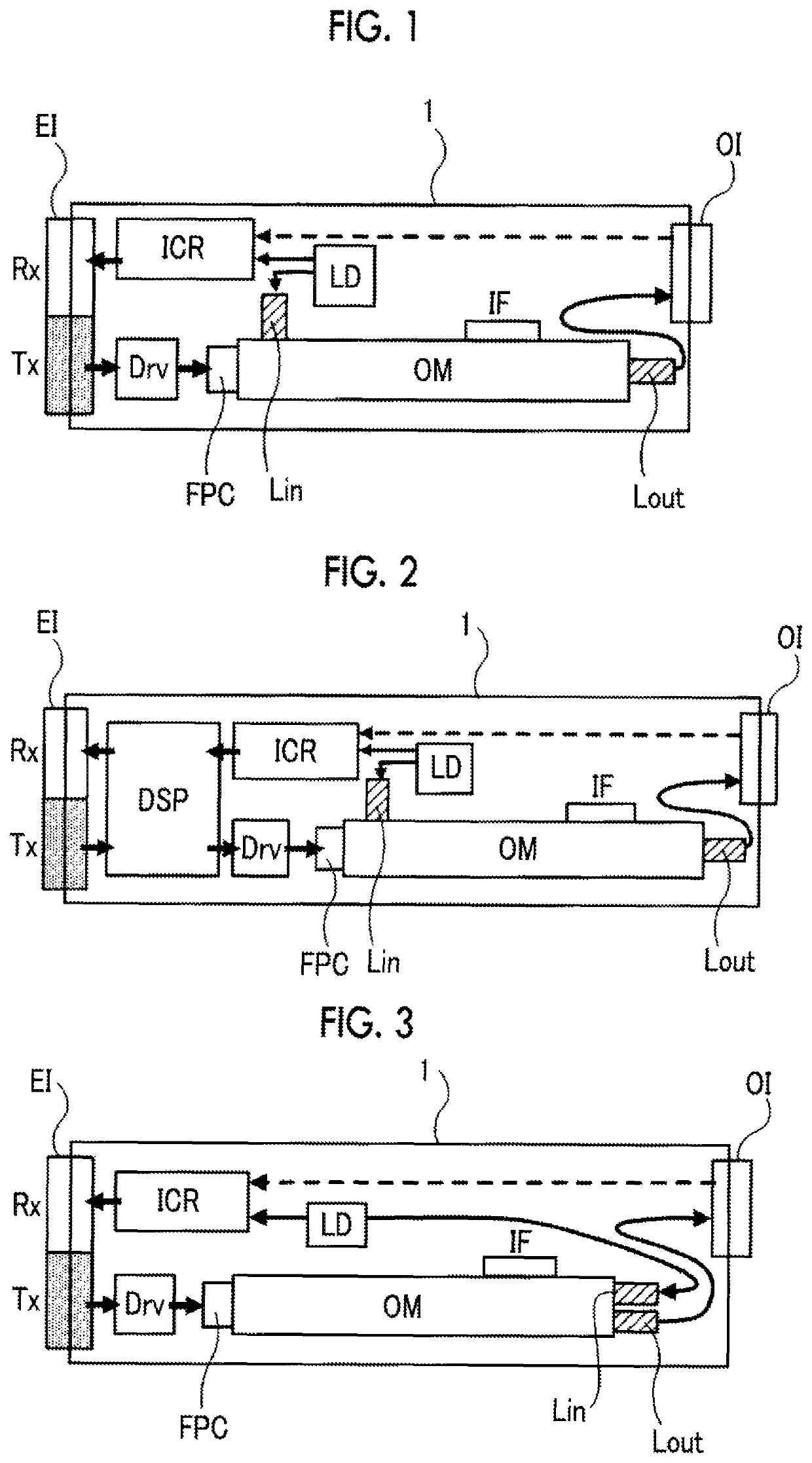
The present invention aims to solve the problem of high-frequency signal loss in optical communication modules. It provides a solution to miniaturize such modules while suppressing signal loss. An optical communication module is presented that includes an optical modulator with a driver circuit and an electrical interface, and an optical interface. The module has a wiring substrate that introduces the high-frequency signal to the optical modulation element, and the driver circuit is positioned between the wiring substrate and the electrical interface. The optical modulator is housed in a rectangular parallelepiped container, and the end of the wiring substrate is led out from one short-side side of the container. This design results in a small module size and suppressed signal loss.

Problems solved by technology

However, in a case where optical components such as the optical modulator and electrical components such as the driver circuit are integrally disposed in a narrow space, not only connection between the optical components but also handling of interconnections through which a high-frequency signal propagates become complex, thereby conversely causing performance deterioration of the optical communication module.

Method used


Image

  • Optical communication module and optical modulator used therein
  • Optical communication module and optical modulator used therein
  • Optical communication module and optical modulator used therein

Examples


Embodiment Construction

[0028]Hereinafter, an optical communication module and an optical modulator that is used in the optical communication module according to the invention will be described in detail with reference to preferred examples.

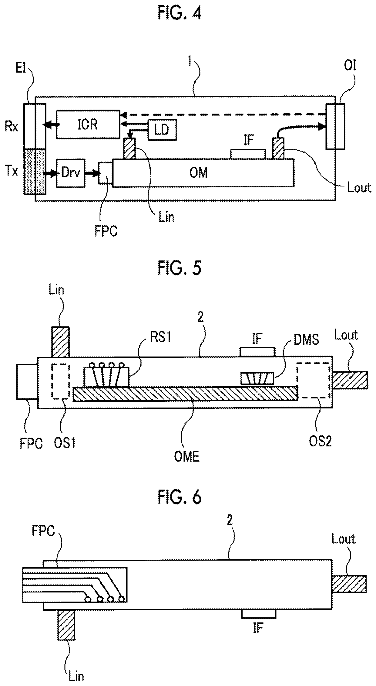
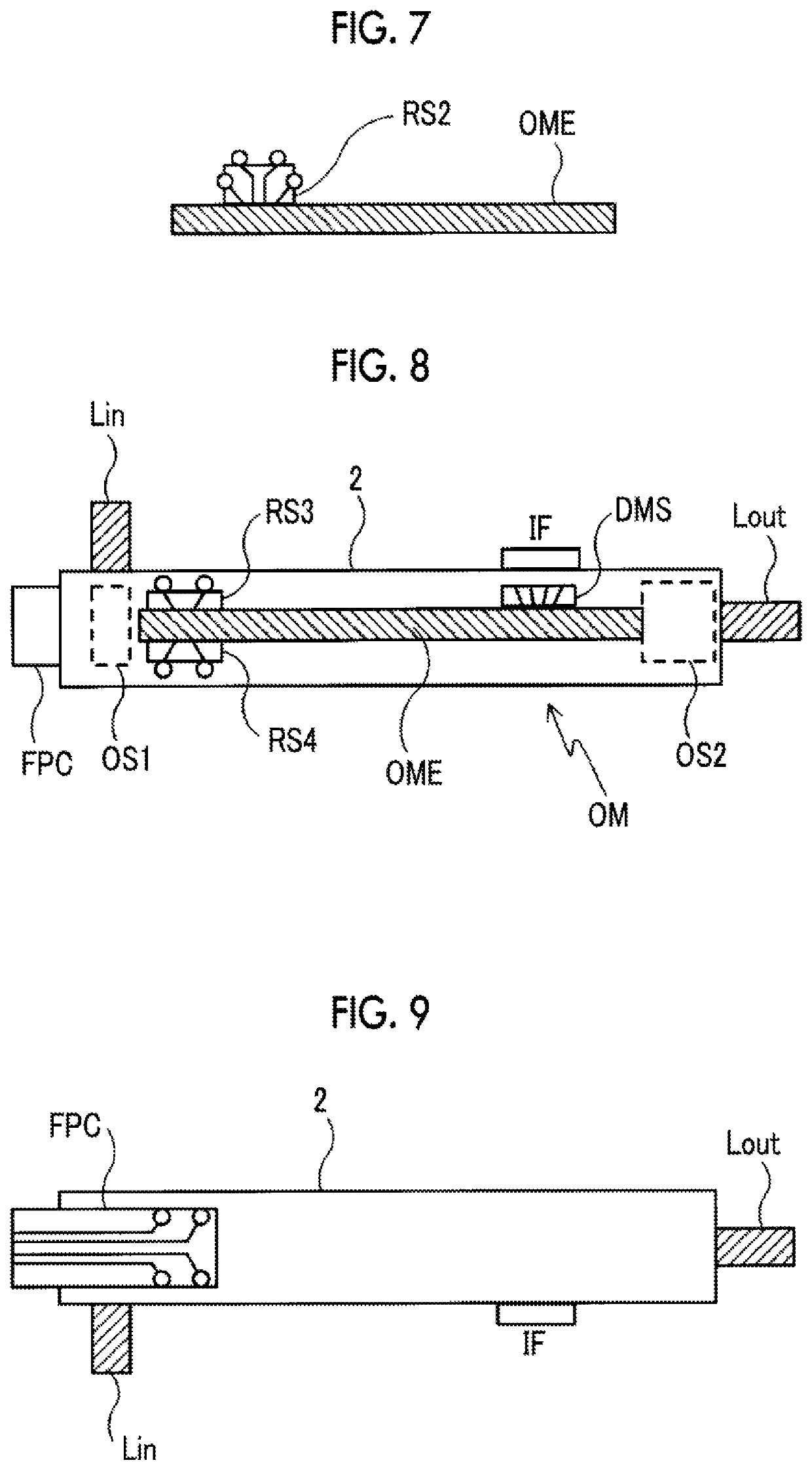
[0029]As illustrated in FIG. 1 to FIG. 4, the optical communication module of the invention includes an optical modulator OM that includes an optical modulation element housed in a rectangular parallelepiped container, a driver circuit Drv that inputs a high-frequency signal to the optical modulation element, and a housing 1 that houses the optical modulator OM and the driver circuit Drv. An electrical interface EI is provided on one lateral surface of the housing, and an optical interface OI is provided on another lateral surface, which is opposite to the lateral surface, of the housing. In the optical modulator OM, an end of a wiring substrate FPC, which is configured to introduce the high-frequency signal to the optical modulation element, is led out from one short-s...


PUM

PropertyMeasurementUnit
frequencyaaaaaaaaaa
transmission capacityaaaaaaaaaa
electricalaaaaaaaaaa

Abstract

An optical communication module includes: an optical modulator that includes an optical modulation element housed in a rectangular parallelepiped container; a driver circuit that inputs a high-frequency signal to the optical modulation element; and a housing that houses the optical modulator and the driver circuit. An electrical interface is provided on one lateral surface of the housing, and an optical interface is provided on another lateral surface, which is opposite to the lateral surface, of the housing. In the optical modulator, an end of a wiring substrate, which is configured to introduce the high-frequency signal to the optical modulation element, is led out from one short-side side of the rectangular parallelepiped container, and the driver circuit is disposed between the short-side side of the optical modulator and the electrical interface.

Description

CROSS-REFERENCE TO RELATED APPLICATIONS[0001]This application claims the benefit of Japanese Patent Application No. 2017-072909 filed Mar. 31, 2017, the disclosure of which is herein incorporated by reference in its entirety.BACKGROUND OF THE INVENTIONField of the Invention[0002]The present invention relates to an optical communication module and an optical modulator that is used in the optical communication module, and particularly to an optical communication module in which an optical modulator and a driver circuit are disposed in a housing, and an optical modulator that is used in the optical communication module.Description of Related Art[0003]In an optical communication field, an optical transmission module in which an optical modulator and a driver circuit are embedded in a housing, or an optical transmission and reception module in which the optical modulator and an optical receiver are embedded in the housing is put into practical use. The optical communication modules are u...

Claims


Application Information

Patent Timeline
Patent Type & Authority Patents(United States)
IPC IPC(8): G02F1/03G02F1/035H04B10/50
CPCG02F1/0327G02F1/035H04B10/50G02F2202/20G02B6/4274G02B6/4279H04B10/40H04B10/516
Inventor MIYAZAKI, NORIKAZUKATOU, KEI
Owner SUMITOMO OSAKA CEMENT CO LTD
Learn More