Transmission apparatus, printed circuit board, and information appliance

a technology of transmission apparatus and printed circuit board, which is applied in the direction of waveguides, high frequency circuit adaptations, waveguide type devices, etc., can solve the problems of reducing the manufacturing difficulty of circuit boards, and reducing the production efficiency of circuit boards. , to achieve the effect of suppressing propagation loss

Pending Publication Date: 2022-09-15
SONY SEMICON SOLUTIONS CORP
View PDF0 Cites 0 Cited by
  • Summary
  • Abstract
  • Description
  • Claims
  • Application Information

AI Technical Summary

Benefits of technology

[0029]According to the technology disclosed in this specification, a transmission apparatus, a printed circuit board, and an information appliance that have a transmission line into which a low-impedance part is inserted, such as a printed circuit board on which a circuit chip is mounted, and suppress propagation loss due to mismatched impedance can be provided.
[0030]Note that the advantageous effects described in this specification are merely for the sake of example, and the advantageous effects of the present invention are not limited thereto. Furthermore, in some cases the present invention may also exhibit additional advantageous effects other than the advantageous effects given above.
[0031]Further objectives, features, and advantages of the technology disclosed in this specification will be clarified by a more detailed description based on the exemplary embodiments described hereinafter and the attached drawings.

Problems solved by technology

It is known that the presence of mismatched impedance on a transmission line causes reflections and degradation in the propagation characteristics.
For example, in an apparatus that handles high-frequency signals such as millimeter waves, large reflections occur, and therefore the above problem becomes more apparent.
However, as the frequency of the transmission signal goes higher, the wavelength A shortens and the distance between the land and the via hole becomes shorter, and consequently there are concerns about the increased difficulty of the circuit board manufacturing.
However, it is necessary to mount the line immediately before the structure that causes reflections.

Method used


Image

  • Transmission apparatus, printed circuit board, and information appliance
  • Transmission apparatus, printed circuit board, and information appliance
  • Transmission apparatus, printed circuit board, and information appliance

Examples


Embodiment Construction

[0042]Hereinafter, an embodiment of the technology disclosed in this specification will be described in detail with reference to the drawings.

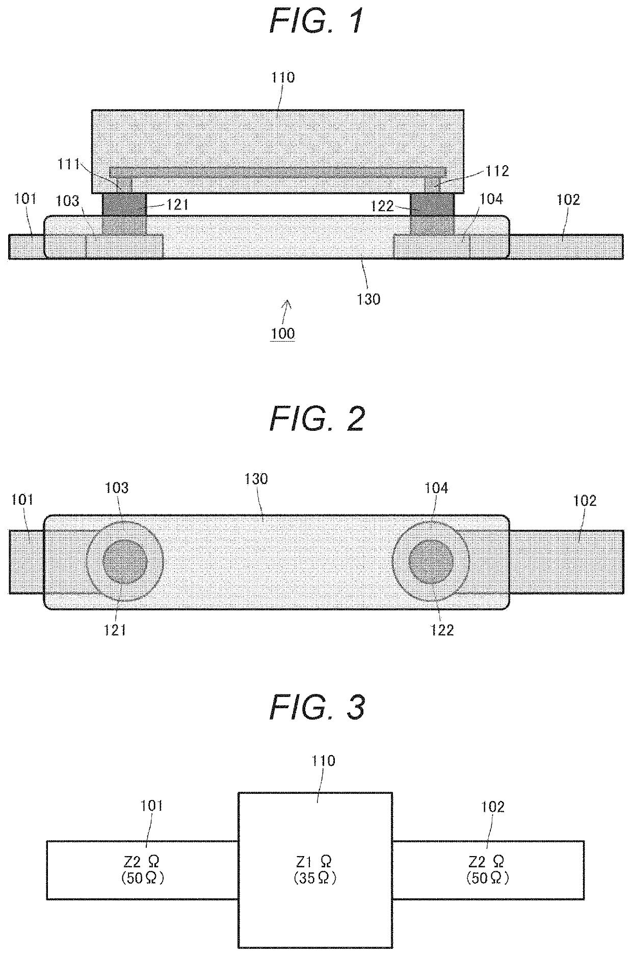
[0043]FIGS. 1 and 2 illustrate an exemplary configuration of a printed circuit board 100 envisioned in the present embodiment. However, FIG. 1 illustrates a view seen from the side of the printed circuit board 100 with a circuit chip 110 mounted thereon, while FIG. 2 illustrates a view seen from the top of the printed circuit board 100 (and with the circuit chip 110 removed).

[0044]The circuit chip 110 is mounted onto the printed circuit board 100. The circuit chip 110 is an electronic component also referred to as a “package”. Here, a high-frequency circuit that handles signals such as millimeter-wave signals for high-speed wireless communication for example is anticipated as the circuit chip 110.

[0045]Interconnects 101 and 102 containing copper foil or the like are formed by lithographic technology on the top face of the printed circuit board...


PUM


Abstract

There is provided a transmission apparatus having a transmission line into which a low-impedance part is inserted. The transmission apparatus includes a package having a first impedance, a first transmission line and a second transmission line respectively connected on either side of the package and having a second impedance different from the first impedance, and an intermediate section respectively disposed in a connection between the package and the first transmission line and in a connection between the package and the second transmission line. The intermediate section is adjusted to have an electrical length of λ/4 (where λ is an electromagnetic wavelength corresponding to a desired frequency) and an impedance that is intermediate between the first impedance and the second impedance.

Description

TECHNICAL FIELD[0001]The technology disclosed in this specification relates to a transmission apparatus, a printed circuit board, and an information appliance having a transmission line into which a low-impedance part is inserted.BACKGROUND ART[0002]It is known that the presence of mismatched impedance on a transmission line causes reflections and degradation in the propagation characteristics. For example, in an apparatus that handles high-frequency signals such as millimeter waves, large reflections occur, and therefore the above problem becomes more apparent.[0003]For example, for a circuit board on which a semiconductor chip is mounted, a semiconductor apparatus and a circuit board have been proposed in which impedance matching is achieved by disposing a through-hole with a large via land at a location distanced by λ / 4 the electrical length (where λ is the electromagnetic wavelength corresponding to a desired frequency) from an electrode (land) electrically connected to the semi...

Claims


Application Information

Patent Timeline
Patent Type & Authority Applications(United States)
IPC IPC(8): H01P3/08H05K1/02H05K1/11
CPCH01P3/08H05K1/0237H05K1/11H01L23/12H01P5/028H01P1/127H05K1/024H05K1/0243H05K1/025H05K1/181
Inventor SAWADA, KAZUYA
Owner SONY SEMICON SOLUTIONS CORP
Why Eureka
Try Eureka