
Minor axis motion type ultrasonic probe

a motion-type, ultrasonic probe technology, applied in the field of minor axis motion-type ultrasonic probes, can solve the problems of affecting the normal transmission and reception of ultrasonic waves to and from a living body, and affecting so as to suppress the propagation loss of ultrasonic waves and improve the sensitivity of the probe. , the effect of increasing the curvature of the lens

Active Publication Date: 2012-04-24
NIHON DEMPA KOGYO CO LTD
View PDF9 Cites 1 Cited by
  • Summary
  • Abstract
  • Description
  • Claims
  • Application Information

AI Technical Summary

Benefits of technology

The present invention relates to an ultrasonic imaging device. The technical effects of this invention include the use of a concave lens made of a resin with a high acoustic velocity but low propagation loss, and the use of a liquid with a lower acoustic velocity than the living body as an ultrasonic wave medium. These effects allow for a thinner concave lens and improved image quality.

Problems solved by technology

In a case where the sealed container 3 is not filled with the liquid l and air is present in between the inner wall surface 3b1 of the cover 3b and the surface of the piezoelectric element group 1, attenuation of ultrasonic waves is significant and propagation efficiency is deteriorated, so that normal transmission and reception of ultrasonic waves to and from a living body cannot be expected.
However, in the conventional ultrasonic probe having the above configuration, since the acoustic lens 2 (convex lens) is formed from a silicone resin (rubber), the propagation loss of ultrasonic waves is significant.
Consequently, the thickness of the acoustic lens 2 in the center section becomes greater, and hence the propagation loss becomes more significant.
Therefore, there has been a problem in that as the propagation loss increases the sensitivity of the ultrasonic probe is reduced.

Method used


Image

  • Minor axis motion type ultrasonic probe
  • Minor axis motion type ultrasonic probe
  • Minor axis motion type ultrasonic probe

Examples


Embodiment Construction

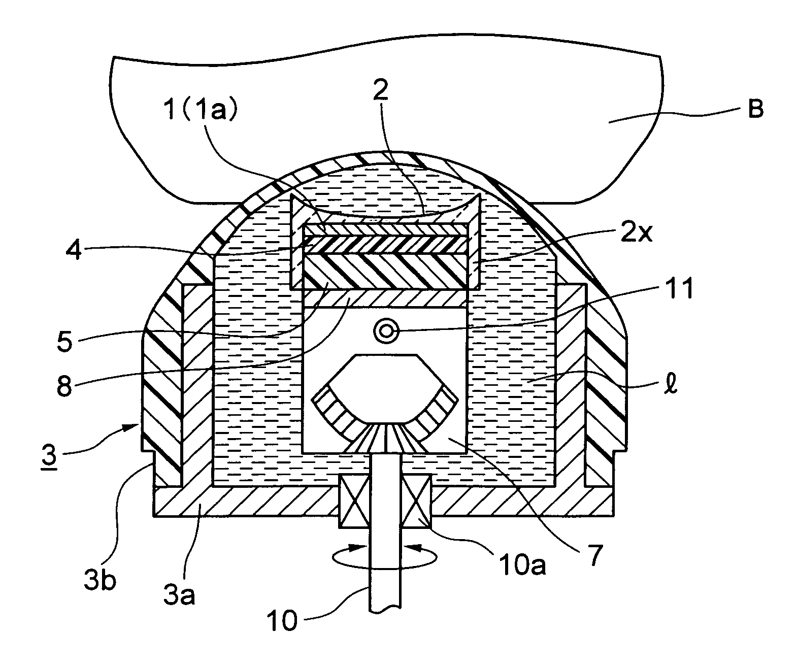
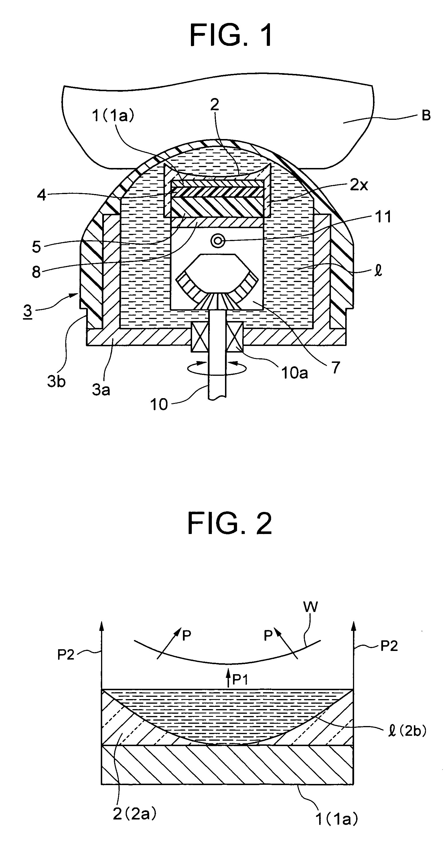
[0033]FIG. 1 is a minor axis direction sectional view for describing an embodiment of an ultrasonic probe of the present invention.

[0034]The ultrasonic probe of the present invention is configured such that a piezoelectric element group 1 arranged in the major axis direction and with an acoustic lens 2 having a predetermined curvature in the minor axis direction provided on an ultrasonic wave transmitting / receiving surface side, is housed within a sealed container 3.

[0035]The inside of the sealed container 3 is filled with a liquid l that serves as an ultrasonic wave medium, and the piezoelectric element group 1 is fixed on a fixed base 8 that rotates / oscillates within a container main body 3a, so as to rotate / oscillate in the minor axis direction of the ultrasonic probe. Furthermore, ultrasonic waves from a cover 3b side are transmitted / received to / from a living body B.

[0036]Moreover, in this embodiment, the acoustic lens 2 is made as a concave lens 2a having a pair of leg sections...


PUM


Abstract

The invention relates to a minor axis motion type ultrasonic probe with high sensitivity that suppresses propagation loss. The minor axis motion type ultrasonic probe of the invention comprises: a piezoelectric element group in which a plurality of piezoelectric elements are arranged in a line in a major axis direction of the piezoelectric element group; an acoustic lens that is provided on an ultrasonic wave transmitting / receiving surface side of the piezoelectric element group and that has a predetermined curvature in a minor axis direction of the piezoelectric element group; and a sealed container that houses the piezoelectric element group with the acoustic lens provided thereon and that is filled with a liquid serving as an ultrasonic wave medium, and the piezoelectric element group is moved in the minor axis direction and ultrasonic waves are transmitted and received to and from a living body, wherein the configuration is such that the acoustic lens is a concave lens formed from a material that has less propagation loss than a silicone resin and that has a greater acoustic velocity than a living body, and a relationship between acoustic velocity c1 of the concave lens, acoustic velocity c2 of the liquid, and acoustic velocity c3 of the living body is expressed as c1>c3>c2.

Description

TECHNICAL FIELD[0001]The present invention relates to a minor axis motion type ultrasonic probe that rotates / oscillates or linearly reciprocates in the minor axis direction of a piezoelectric group, and in particular relates to an acoustic lens provided on an ultrasonic wave transmitting / receiving surface formed on a front surface of the piezoelectric element group.PRIOR ART[0002]In a minor axis motion type ultrasonic probe, a piezoelectric element group serving as an ultrasonic wave generating source, is mechanically scanned in the minor axis direction thereof, and is electronically scanned in the major axis direction thereof. Therefore, a minor axis motion type ultrasonic probe has recently drawn attention because compared for example to a matrix type that electronically scans in either the minor axis direction or the major axis direction, it makes electrical wiring easier and enables acquisition of a three dimensional image.[0003]FIG. 5 is a drawing for describing a conventional ...

Claims


Application Information

Patent Timeline
Patent Type & Authority Patents(United States)
IPC IPC(8): A61B8/00
CPCA61B8/14
Inventor MATSUZAWA, ITARU
Owner NIHON DEMPA KOGYO CO LTD
Learn More