Defoaming method and device

a defoaming device and foaming technology, applied in mechanical vibration separation, other chemical processes, separation processes, etc., can solve the problems of insufficient available time to destroy foam, difficult to reduce the amount of oxygen in the head space, and foam remains during sealing, so as to improve the energy utilization efficiency, reduce the content to be affected by high-power lasers, and reduce the effect of oxidation

Active Publication Date: 2016-03-15
TOYO SEIKAN KAISHA LTD
View PDF27 Cites 0 Cited by
  • Summary
  • Abstract
  • Description
  • Claims
  • Application Information

AI Technical Summary

Benefits of technology

[0028]According to the present invention, use of the acoustic waveguide generates an effect of condensing the energy of shock waves, most of which have conventionally been released into free space, to the direction toward the open end. Since the utilization efficiency of energy increases, the illumination point can be more distant from the liquid surface compared with conventional techniques. Thereby fewer restrictions are imposed on the condensing optical system, and a more efficient condensing optical system can be constructed.
[0029]The laser beam is irradiated in a direction approximately perpendicular to the axis of the acoustic waveguide, therefore irradiating the laser beam onto the liquid surface can be prevented, and the possibility of the content to be affected by the high power laser can be eliminated. Since the laser beam path and the traveling path of the shock wave can be separated, fewer restrictions are imposed on the condensing optical system, and a condensing optical system with high breakdown efficiency can be constructed.
[0030]Furthermore, the reflecting condensing element is disposed at the end of the laser beam, whereby the light which was not used for the laser induced breakdown can be used to strengthen breakdown, which improves efficiency and increases safety.
[0031]Furthermore, the acoustic impedance is matched between the acoustic waveguide and the external space, whereby propagation loss of the sound waves at the open end can be suppressed.
[0032]Furthermore, the acoustic waveguide is formed to be a bent tube, so that the plasma light of the illumination point cannot be directly seen from the open end, whereby the plasma light is absorbed by the wall surface of the acoustic waveguide and cannot reach the open end, and the possibility of the plasma light to affect the content can be eliminated.
[0033]Furthermore, gas is supplied into the acoustic waveguide, whereby entry of outside air through the open end can be prevented. Normally steam is generated from the content which is filled, and the presence of the gas supplied here can prevent contamination caused by this steam entering the acoustic waveguide. It is preferable that the inlet of the gas is located between the illumination point and the open end, then ozone, generated by oxygen in the air that is ionized during laser induced breakdown, to flow out of the open end and enter a container, such as a can, can be prevented.

Problems solved by technology

Foam generation behavior and disappearing behavior of the generated foam differ depending on the properties of an individual beverage and the filling conditions, but typically when the production rate is high, a large amount of foam is generated, available time is insufficient to destroy foam, and foam remains during sealing.
Foam contains oxygen at the same concentration level as air, and because the oxygen contained in the foam cannot be removed by gas displacement in the head space, the foam makes it difficult to decrease the amount of oxygen in the head space.
However with conventional defoaming methods using light irradiation, the defoaming rate is low, and does not match with increased filling speeds.
As a result, such methods have not found practical use.
Because time allocated for the defoaming process in the accelerated filling process is short, a sufficient defoaming effect cannot be obtained with a light intensity obtained with a standard light source.
Conversely, a high power light source is needed to produce energy sufficient to attain the defoaming effect, and such a light source is impractical.
On the other hand, when defoaming employs irradiation with ultrasonic waves, for example, if defoaming is performed by irradiating with continuous ultrasonic waves generated by an external sound source, because the wavelength of ultrasound is of the same order as the size of the container, that is the irradiation object, the waves lack directivity, irradiation energy is dissipated, and efficiency is poor.
As a result, defoaming must be performed over a long distance on a conveyor, and the production line becomes long.
Accordingly such an approach is undesirable from the standpoint of saving space.
Furthermore in the case of narrow mouth containers, such as PET bottles or bottle cans, it is difficult to transmit light, sound, etc. to the entire liquid surface through the mouth opening, hence there is no effective defoaming means.
Another problem associated with conventional methods is that it is virtually impossible to destroy foam that adheres to the inner surface of the container.
This makes electrode life short, therefore the arc electrode must be replaced periodically.
This replacement operation contaminates the filling space, and if the filling is asceptic, sanitation is negated.
The electrode material also causes scattering, and contamination is caused by the scattering as well.
Furthermore, the discharge position is unstable, which results in dispersion of the defoaming effect.
According to this method, the pulsed sound waves cause a strong pressure change from the sound source propagating as spherical waves, destroying foam.
Since pulsed sound waves propagate all the way to the inner peripheral surface of a container, foam adhering to the inner peripheral surface of the container, of which defoaming has been difficult with conventional methods, can be effectively destroyed.

Method used


Image

  • Defoaming method and device
  • Defoaming method and device
  • Defoaming method and device

Examples


Embodiment Construction

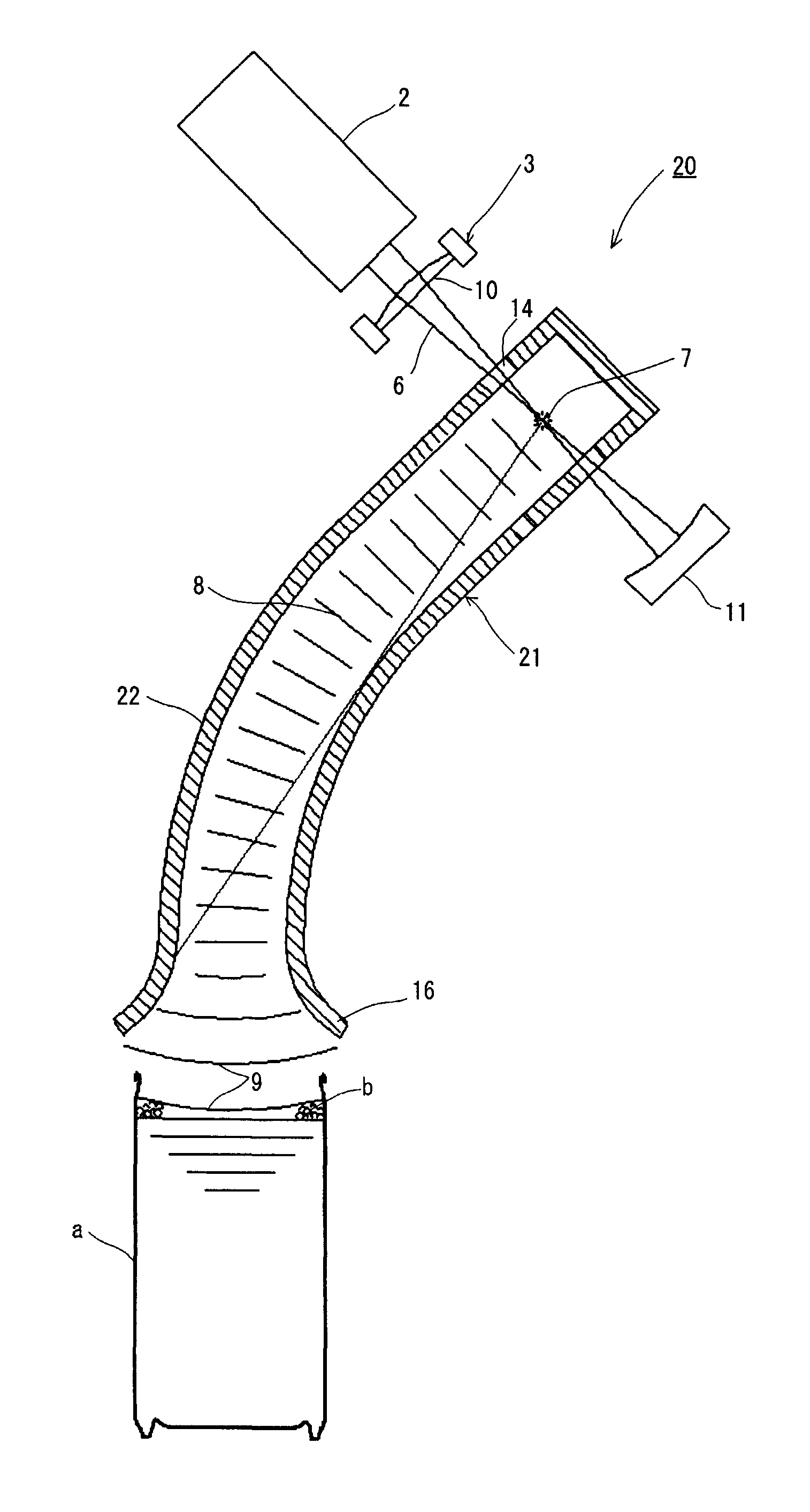
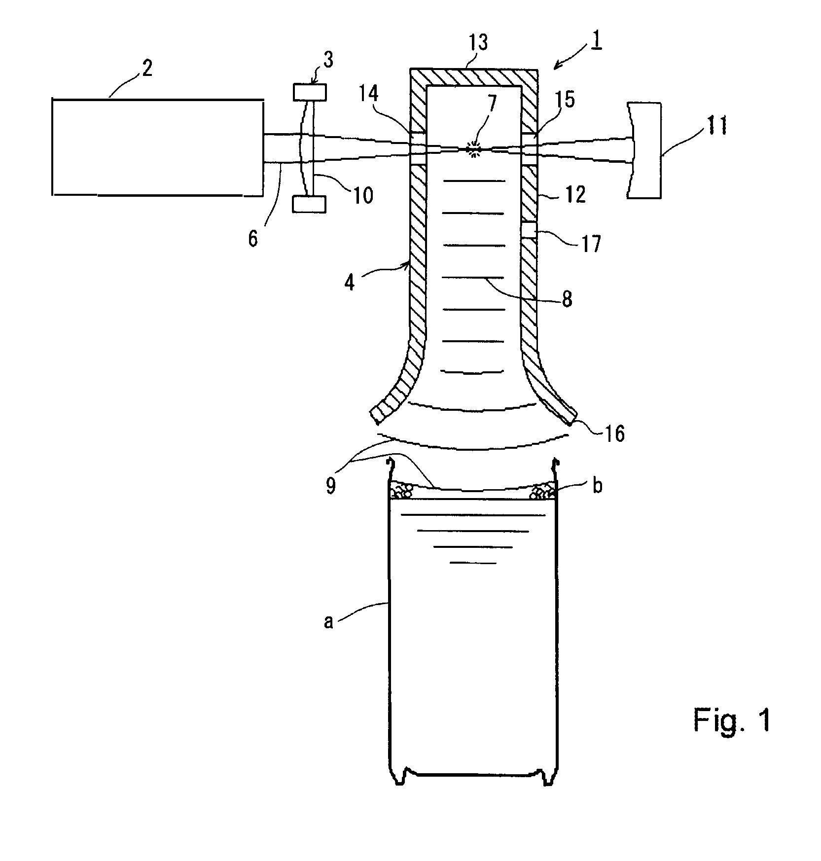
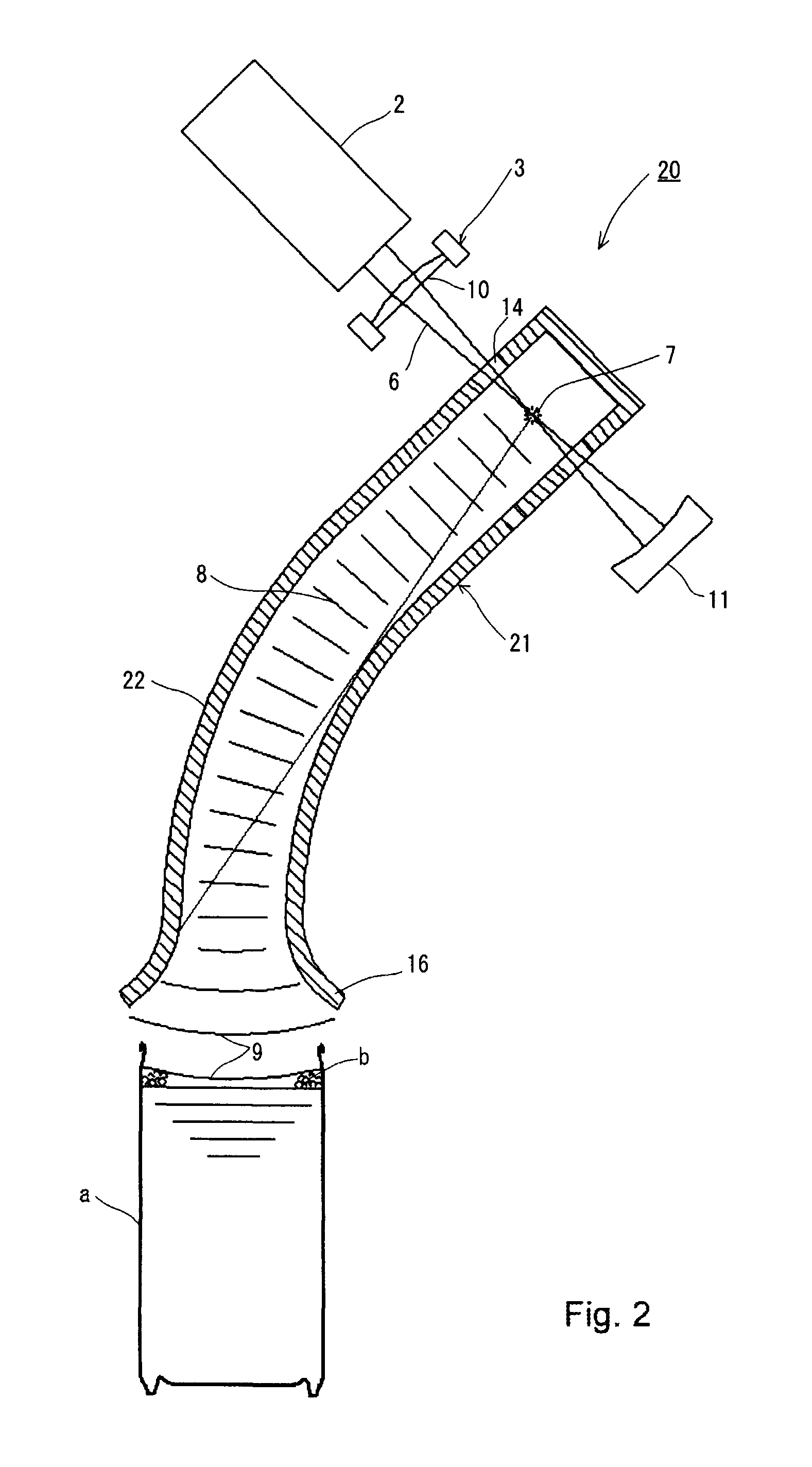
[0058]In a defoaming method according to the present embodiment, a pulsed laser beam is condensed and irradiated onto an internal space of an acoustic waveguide so as to generate pulsed sound waves from an illumination point as a sound source, and foam outside an open end of the acoustic waveguide is destroyed by the pulsed sound waves propagating through the acoustic waveguide, and FIG. 1 schematically illustrates the basic structure of defoaming principle of the defoaming method.

[0059]In FIG. 1, the reference numeral 1 stands for a defoaming device according to this embodiment, which comprises a pulsed laser beam oscillation device 2 that generates a pulsed light beam, a condensing optical system 3 that condenses the pulsed laser beam oscillated by the pulsed laser beam oscillation device, and an acoustic waveguide 4, and in this configuration, an open end 16 of the acoustic waveguide is located above the liquid surface of a defoaming object facing the liquid surface in the vertic...


PUM

PropertyMeasurementUnit
acoustic impedanceaaaaaaaaaa
volumeaaaaaaaaaa
concentrationaaaaaaaaaa

Abstract

Provided are a deforming method and device that use laser-induced breakdown. The provided method and device make it possible to shorten the focal distance, thereby improving laser beam convergence, and increase the utilization efficiency of sound waves that contribute to defoaming. Pulsed laser light is focused and irradiated into a space inside an acoustic waveguide (4), thereby generating pulsed sound waves from the illumination point (7). The pulsed sound waves propagate down the acoustic waveguide as plane waves, then propagate beyond an open end (16) as spherical waves, and break up a foam outside the open end of the acoustic wave guide.

Description

TECHNICAL FIELD[0001]The present invention relates to a defoaming method and defoaming device suitable for defoaming foam on a liquid surface, in particular, destroying foam generated when a container, such as a can, a PET bottle, a bottle can and a pouch, is filled with a liquid, such as a beverage.BACKGROUND ART[0002]In a filling process of producing packaged beverages (canned beverages, beverages in PET bottles, bottled beverages), a beverage is typically flowed from above into a container disposed vertically in a filling machine, then the container is joined to a lid member and sealed in a sealing machine (a seaming machine, a capper and the like). In order to maintain the beverage quality and to improve flavor, it is important to reduce the amount of residual oxygen in the sealed container. The removal of oxygen from the head space inside the container is especially important. A deoxidation technique, such as undercover gas displacement, performed immediately prior to sealing h...

Claims


Application Information

Patent Timeline
Patent Type & Authority Patents(United States)
IPC IPC(8): B01D19/02B65B3/22
CPCB01D19/02B65B3/22C02F1/20H01S3/00
Inventor TAKENOUCHI, KEN
Owner TOYO SEIKAN KAISHA LTD
Why Eureka
Try Eureka