
Production process for stamped parts of high mechanical resistance, through controlled electric heating

a production process and high mechanical resistance technology, applied in the metallurgical industry, can solve the problems of better equipment operating costs and equipment operating costs, and achieve the effects of improving heating efficiency, improving operating costs, and improving heating efficiency

Active Publication Date: 2020-02-04
AETHRA SISTEMAS AUTOMOTIVOS
View PDF9 Cites 1 Cited by
  • Summary
  • Abstract
  • Description
  • Claims
  • Application Information

AI Technical Summary

Benefits of technology

[0011]To the extent of improving these rates and increasing heating efficiency, the present invention provides a heating process by conduction (heating by Joule effect), which uses a small size heating device, occupying a smaller area and thus providing a better utilization of the area used by the production line, and furthermore allowing heating up to 400° C. / sec, with a speed higher than twice as fast as induction heating and 61 times faster than radiation heating. Thus, with regard to the efficiency of the process, i.e. the efficiency of energy utilization to carry out the heating of the plate, heating by conduction can reach 87%, promoting a major economy in costs of transforming metal sheets.
[0013]Moving both hot and cold parts can be done by both robotic arms and dedicated moving “transfer” systems designed specifically for the applications and in the case of hot part moving they are constructed of material that supports temperature and radiation from the plate without getting damaged.
[0014]The heating method used in the process in question is more energy efficient than other heating elements normally used to raise the temperature of the work piece to be tool hardened, thus having a better cost as regards the operating costs of the equipment. Also because it promotes the rapid heating of the parts, it is possible to decrease the quantities of parts in process and the space occupied due to the characteristics of the equipment and of the applied process.
[0015]The heating of plates by joule effect, used in the product in question, has a high energy efficiency, around 80 to 90%. Together with the control and moving systems of the parts, it promotes a production line that is more energy-efficient, space-efficient and with shorter cycle times.

Problems solved by technology

The heating method used in the process in question is more energy efficient than other heating elements normally used to raise the temperature of the work piece to be tool hardened, thus having a better cost as regards the operating costs of the equipment.

Method used


Image

  • Production process for stamped parts of high mechanical resistance, through controlled electric heating

Examples


Embodiment Construction

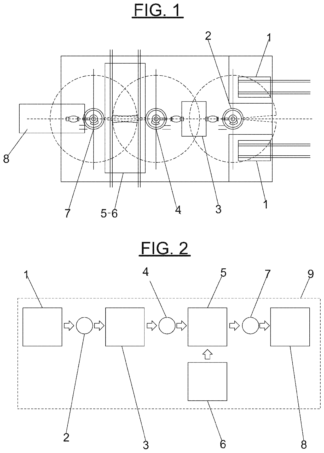
[0019]According to these figures and their numerical references, the subject of this invention relates to a production process for high-strength parts through automatic controlled electric heating using a tool hardening procedure (mold and press). Said process is implemented from bales of feed sheets (1), a first moving robot (2), a heating device (3), a second moving robot (4), a specific molding tool (5) with a liquid cooling unit (6), a third moving robot (7), a hydraulic press (8). All equipment is controlled by an electronic control unit (9).

[0020]In practice, the pieces, in the form of plates of various shapes (with or without defined figures), are fed to the production line automatically through bales of sheets (1), being moved by the first manipulation robot (2), which withdraws one plate at a time and deposits it in the electric heating equipment (3). This electric heating equipment (3) employs the joule heating theory raising the temperature of the plate to values around 9...


PUM

PropertyMeasurementUnit
temperatureaaaaaaaaaa
lengthaaaaaaaaaa

Abstract

A production process for stamped parts carried out from bales of sheets (1), a first moving robot (2), a heating device (3) with a liquid cooling unit (4), a second moving robot (4), a hydraulic press (5) with a specific molding tool, a third moving robot (6), and a conveyor belt (8), controlled by an electronic control unit. Said specific molding tool is provided with channels for cooling done through heat exchange, via water circulation, where the cooling rate is controlled by means of the liquid's flow and temperature control.

Description

FIELD OF THE INVENTION[0001]This invention, relating to the metallurgical industry, particularly in the field of auto parts, is about a production process for stamped parts, which shows a significant improvement in efficiency, by means of controlled electric heating.BACKGROUND OF THE INVENTION[0002]The production of stamped parts of high hardness from the high temperature forming process consists of heating a metal sheet (specific material) and then hardening of this material, by transforming the microstructure of the metallic material to conditions of higher hardness through quick cooling of the sheet already formed into its final shape inside the tool. This requires heating the plate from room temperature to the temperature called austenitizing temperature of the material, when its microstructure will have been transformed into austenite.[0003]In this process, after heating, the work piece is conveyed automatically to a stamping mold located inside a press. The mold or tool, as is...

Claims


Application Information

Patent Timeline
Patent Type & Authority Patents(United States)
IPC IPC(8): B21D22/02C21D1/42C21D1/673B21D37/16B21D22/20C21D1/40B21J1/06C21D9/46
CPCB21D22/022C21D1/42B21D37/16C21D1/673B21D22/20C21D1/40B21D22/02C21D9/46B21D22/201B21J1/06Y02P10/25
Inventor SPORTELLI, PIETRO
Owner AETHRA SISTEMAS AUTOMOTIVOS
Learn More