
Mine area distributed combined cooling heating power energy system for extracting gas for coal mine

a coal mine and coal mine technology, applied in the direction of gas removal, insulation, borehole/well accessories, etc., can solve the problem of no distributed cchp energy system for gas extraction, and achieve the effect of safe and efficient distributed cchp energy system

Active Publication Date: 2017-03-28
CHINA UNIV OF MINING & TECH
View PDF9 Cites 2 Cited by
  • Summary
  • Abstract
  • Description
  • Claims
  • Application Information

AI Technical Summary

Benefits of technology

This patent describes a system for safely extracting gas from coal mines and utilizing it for energy production. The system includes multiple safeguards to prevent accidents, including a water-sealing flame arrester, wire mesh filter, and a double-effect lithium bromide absorption water chiller / heater unit. The extracted gas is then utilized in a cascaded manner through a gas power machine and waste heat boiler to improve energy utilization efficiency. This system can be adapted for different mining areas and can help reduce emissions of greenhouse gases. Overall, this patent provides a technical solution for efficient and safe extraction and utilization of gas in coal mining areas.

Problems solved by technology

However, owing to the fluctuation of gas concentration in coal mining areas, there is no distributed CCHP energy system for gas extraction in coal mining areas until now, which is constructed specifically on the basis of the characteristics of gas extraction in coal mining areas.

Method used


Image

  • Mine area distributed combined cooling heating power energy system for extracting gas for coal mine
  • Mine area distributed combined cooling heating power energy system for extracting gas for coal mine

Examples


embodiment 1

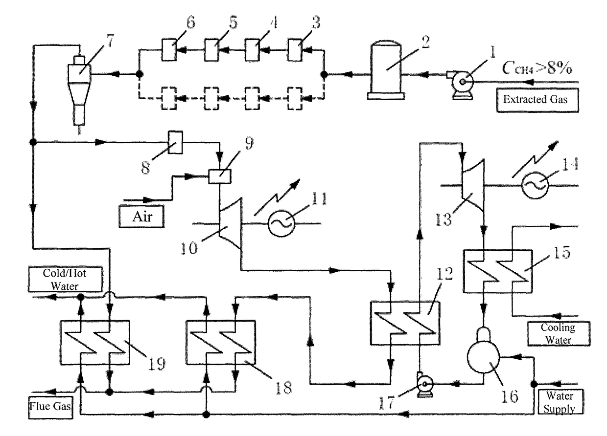
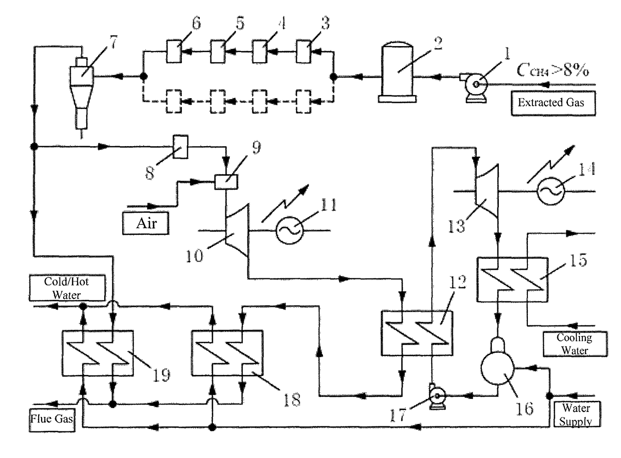
[0039]The combined energy system comprises:[0040]a gas extraction pump station 1, a gas storage tank 2, a water-sealing flame arrester 3, a wire mesh filter 4, a first pipeline flame arrester 5, a wet-type bleeding valve 6, a cyclone dehydrator 7, a second pipeline flame arrester 8, a proportioning mixer 9, a gas power machine 10, a first power generator 11, a waste heat boiler 12, a steam power machine 13, a second power generator 14, a condenser 15, a water storage tank 16, a pressurizing pump 17, a waste heat-type double-effect lithium bromide absorption water chiller / heater unit 18, and a gas-type double-effect lithium bromide absorption water chiller / heater unit 19;[0041]the gas extraction pump station 1, the gas storage tank 2, the water-sealing flame arrester 3, the wire mesh filter 4, the first pipeline flame arrester 5, the wet-type bleeding valve 6 and the cyclone dehydrator 7 are sequentially connected;[0042]the outlet of the cyclone dehydrator 7 is divided into two branc...


PUM


Abstract

A distributed combined cooling, heating and power energy system for gas extraction in a coal mining area, which belongs to an energy system for gas production. A gas extraction pump station, a gas storage tank, a water-sealing flame arrester, a wire mesh filter, a first pipeline flame arrester, a wet-type bleeding valve and a cyclone dehydrator are sequentially connected; an outlet of the cyclone dehydrator is divided into two branches, one branch sequentially connected with a second pipeline flame arrester, a proportioning mixer, a gas power machine, a waste heat boiler and a waste heat-type double-effect lithium bromide absorption water chiller / heater unit, and the other connected with a gas-type double-effect lithium bromide absorption water chiller / heater unit; a first power generator is connected with the gas power machine, a water storage tank outlet is connected with a pressurizing pump, a second power generator is connected with a steam turbine and driven by the steam power machine to generate power, and cold / hot water of the waste heat-type water chiller / heater unit and the gas-type water chiller / heater unit is delivered through an energy supply pipeline after collection and mixing. With the power energy system mining area, clean production and utilization of coal-mine gas and economic development of coal mine areas are realized.

Description

CROSS-REFERENCE TO RELATED APPLICATIONS[0001]This application is a national phase entry under 35 U.S.C. §371 of International Patent Application PCT / CN2014 / 071560, filed Jan. 27, 2014, designating the United States of America and published as International Patent Publication WO 2014 / 187172 A1 on Nov. 27, 2014, which claims the benefit under Article 8 of the Patent Cooperation Treaty to Chinese Patent Application Serial No. 201310202102.7 2013, filed May 24, 2013.TECHNICAL FIELD[0002]This disclosure relates to an energy system for gas production, in particular, to a distributed combined cooling, heating and power (CCHP) energy system for gas extraction in coal mining areas.BACKGROUND[0003]Gas is a companion product of coal, which is a precious non-renewable energy resource. Because the existence of gas is one of the main causes of the frequent accidents in coal mines, gas must be extracted for safe production in coal mines. As the coal mining depth increases, the gas content in the c...

Claims


Application Information

Patent Timeline
Patent Type & Authority Patents(United States)
IPC IPC(8): E21B36/00E21F7/00E21B41/00E21F3/00E21B43/12
CPCE21B36/00E21B36/006E21B41/0085E21B43/122E21F3/00E21F7/00Y02P80/10
Inventor LIN, BAIQUANLI, QINGZHAO
Owner CHINA UNIV OF MINING & TECH
Learn More