
Signal processing circuit

a signal processing circuit and signal processing technology, applied in the direction of amplitude demodulation, digital signal error detection/correction, line-faulst/interference reduction, etc., can solve the problem of deteriorating performance of the maximum likelihood decoder

Inactive Publication Date: 2006-05-16
HITACHI GLOBAL STORAGE TECH JAPAN LTD +1
View PDF10 Cites 0 Cited by
  • Summary
  • Abstract
  • Description
  • Claims
  • Application Information

AI Technical Summary

Benefits of technology

[0011]An object of the present invention is to provide a generally-used method for expanding the distance between signals of a high order partial response system, especially, the EEPRML system and the EEEPRML system irrespective of a code under use. In other words, an object of the present invention is to provide a method for equivalently expanding a distance between signals without newly producing a code rate loss, since the 16 / 17 GCR, or the 8 / 9 GCR used in the PRML signal process operation for a magnetic disk apparatus can be directly applied.
[0031]Next, a description will now be made of an actual method for calculating the asymmetrical coefficients. In a first case of 16 states in EEPRML, the above-explained asymmetrical coefficients are given as (C0=1, C1=2, C2=1). In other words, the value of C0 and the value Of C2 constitute symmetrical coefficients, while setting C1 as a center. To the contrary, in order to calculate the asymmetrical coefficient, first of all, a rear term of a right hand of the formula (3) is set as mornic polynomial of C0=1. Assuming now that the coefficients C1 and C2 are regarded as 2 variable functions of a real number, an optimum coefficient is calculated in accordance with the evaluation basis of the formula (1). Therefore, an integer coefficient most approximated to this real number is calculated. It should be understood that since the methods for calculating the distance between signals, the noise power, and the noise correlative coefficient indicated in the formula (1) are described in detail in the publication “Maximum Likelihood Sequence Estimation of Digital Sequences in the Presence of Intersymbol Interference”, IEEE Transactions on Information Theory, vol. IT-18, No. 3, May 1972, pages 363 to 378, descriptions thereof are omitted. A table 1 represents a typical characteristic of such a partial response that a state number thereof is 16. A distance of an isolated pulse indicated in this table 1 is directly equal to electric power owned by the isolated pulse itself. A minimum distance corresponds to such minimum distance among distances on a trellis diagram of partial response signal having given coefficients. As a consequence, a distance of the minimum distance / isolated pulse may constitute an index for there is a particular improvement in the characteristic. It should also be noted that the characteristics of the table 1 and the table 2 correspond to such a case that the normalized line density is 2.5. Furthermore, according to the present invention, not only the S / N ratio can be improved, but also the length of the code error can be improved, as compared with the long continued errors caused by the conventional EEPRML and EEEPRML systems. That is, giving the utilization efficiency of the energy of the partial response for giving this distance. The partial response system having the coefficient according to the present invention may have the advantages as to this point, as compared with that of the normal EEPRML. As a result, it can be seen that the S / N can be effectively improved with respect to the EEPRML having the symmetrical coefficient. A table 2 represents a typical characteristic of such a partial response that a state number thereof is 32. Also, in this case, according to the present invention, the major error bit length is the 1-bit error bit length, or the 3-bit error bit length. As a consequence, the present invention has such a feature that the error correction can be effectively performed by combining with the error correction code having the code error correcting capability with respect to at least the 1-bit continuous error, and the 3-bit continuous error.

Problems solved by technology

The performance of the maximum likelihood decoder is deteriorated by the adverse influence caused by this correlative relationship of the noise.

Method used


Image

  • Signal processing circuit
  • Signal processing circuit
  • Signal processing circuit

Examples


Embodiment Construction

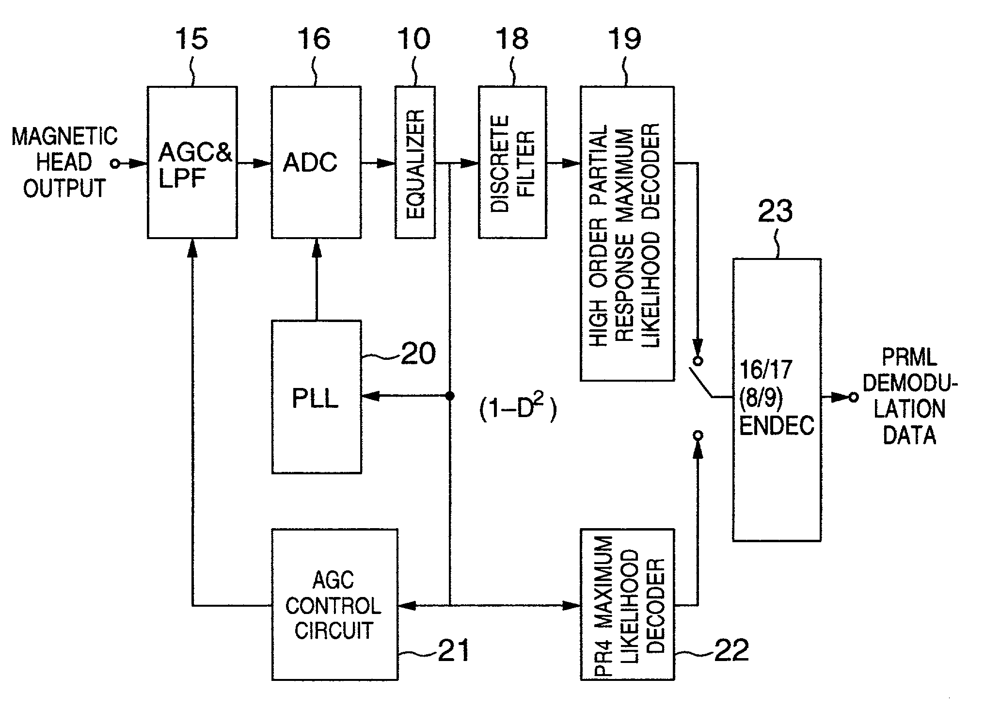
[0049]In FIG. 12, there is shown a structural example of an actual circuit arrangement according to the present invention. First, an output of a magnetic head is supplied via a preamplifier to an AGC (automatic gain control circuit) and LPF (low-pass filter) 15. After this magnetic head output is controlled by the AGC / LPF 15 in such a manner that an amplitude of a signal becomes a constant, noise components other than a desirable frequency range are removed by this AGC / LPF 15. This LPF output signal is discrete-quantized by an ADC 16, and then the discrete-quantized signal is inputted into an equalizer 10. As previously explained, in the equalizer 10, the reproduction signal derived from the magnetic head is equalized in such a manner that this reproduction signal has a partial response characteristic of (1−D2). A clock signal required to operate the ADC 16 is produced from the output signal of this equalizer 10 by a PLL circuit 20. At the same time, a control signal of the AGC / LPF ...


PUM


Abstract

In a data demodulating method, predetermined input data is demodulated based upon a response characteristic of the partial response class 4; the demodulated input data is discrete-filtered to thereby produce filtering data; and the filtering data is maximum likelihood-decoded to thereby produce asymmetrical response data. Further, a magnetic recording / reproducing apparatus is arranged by using this data demodulating method.

Description

CROSS-REFERENCE TO RELATED APPLICATION[0001]The present application is a continuation of application Ser. No. 09 / 124,840, filed Jul. 30, 1998, now U.S. Pat. No. 6,337,889, which relates to subject matter described in U.S. application Ser. No. 08 / 975,670, filed Nov. 28, 1997 entitled A INFORMATION RECORDING / REPRODUCING METHOD AND APPARATUS USING EPRML CONNECTION PROCESSING SYSTEM, now U.S. Pat. No. 6,069,856, the disclosure of which is hereby incorporated by reference.BACKGROUND OF THE INVENTION[0002]The present invention is generally related to a signal processing system for either a magnetic disk apparatus or an optical disk apparatus. More specifically, the present invention is directed to a high-efficiency demodulating method of a high-order partial response system such as an EEPRML (Extended Extended Partial Response Maximum Likelihood) signal processing system and an EEEPRML (Extended EEPRML) signal processing system.[0003]In magnetic disk apparatuses, the partial response maxi...

Claims


Application Information

Patent Timeline
IPC IPC(8): H03D1/00G11B5/035H04B1/10G11B5/00G11B5/012G11B20/14G11B5/09G11B20/10G11B20/18H03M13/23H04B1/00H04L1/00H04L25/08H04L25/497
CPCG11B5/09H04L1/0054G11B20/10055G11B20/10009G11B5/012
Inventor MITA, SEIICHISAWAGUCHI, HIDEKIKOBAYASHI, NAOYAKONDO, MASAHARU
Owner HITACHI GLOBAL STORAGE TECH JAPAN LTD
Learn More