Optical modulation apparatus, method for controlling optical modulator, and control device for optical modulator
a technology of optical modulation and control device, which is applied in the direction of optics, electrical equipment, instruments, etc., can solve the problems of increasing and achieve the effect of reducing the increase of the propagation loss of ligh
- Summary
- Abstract
- Description
- Claims
- Application Information
AI Technical Summary
Benefits of technology
Problems solved by technology
Method used
Image
Examples
first embodiment
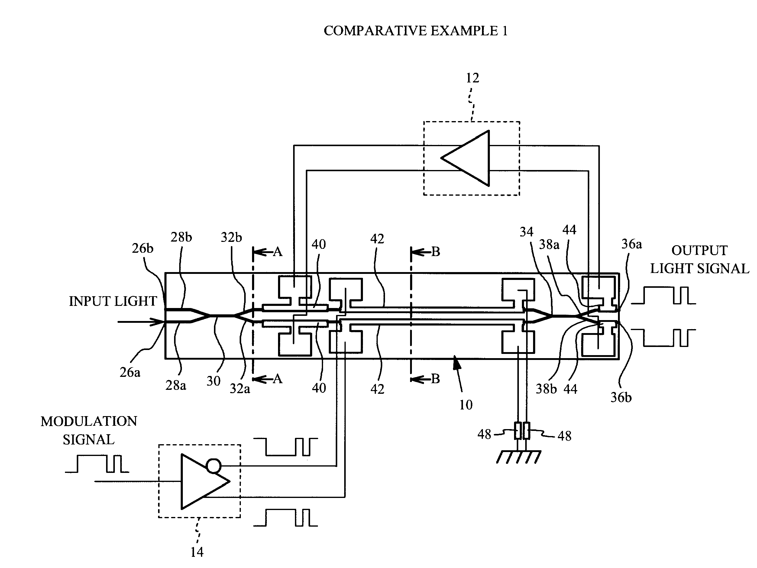
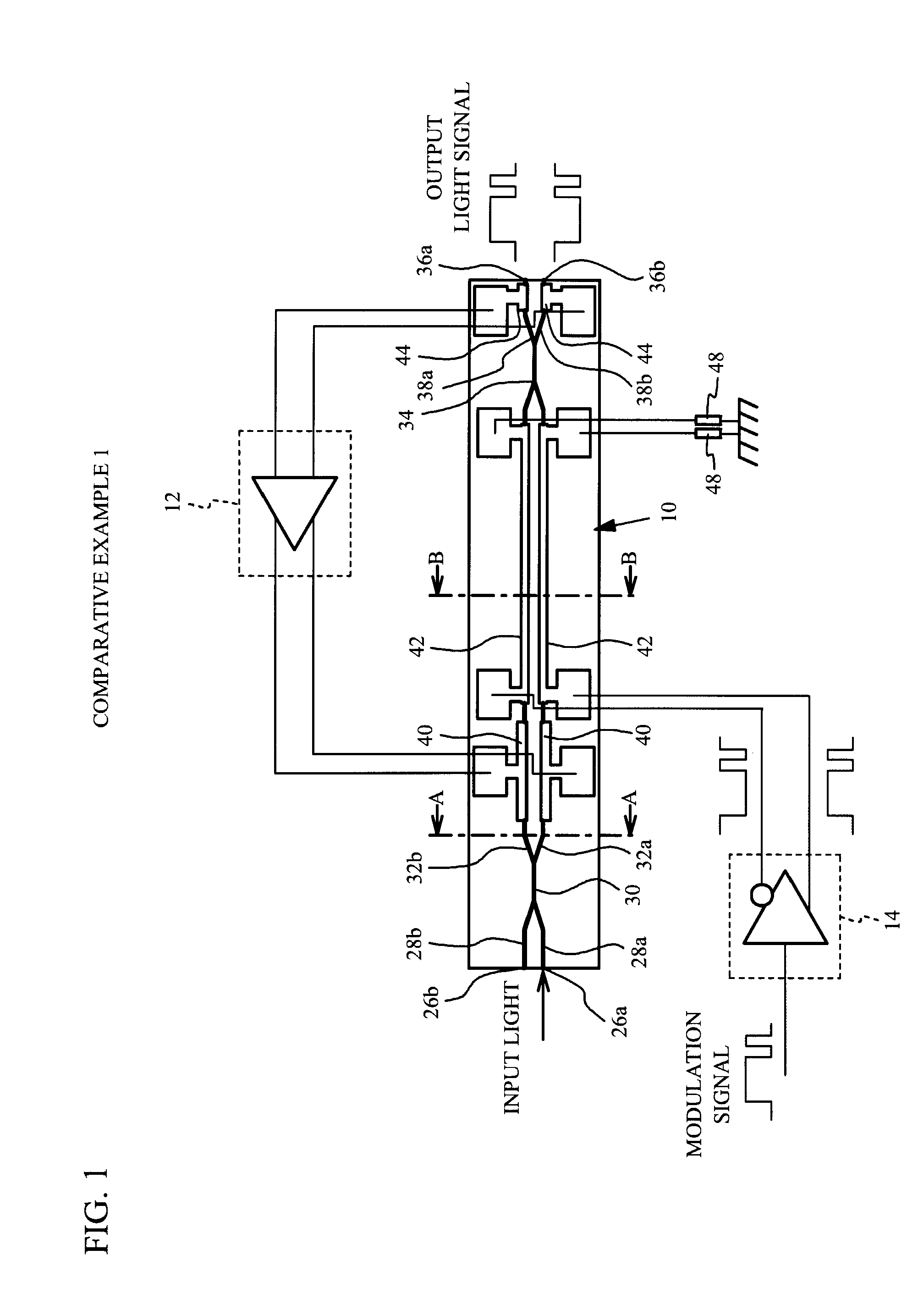
[0042]FIG. 3 is a schematic top view of an optical modulation apparatus according to a first embodiment. As illustrated in FIG. 3, the optical modulation apparatus according to the first embodiment mainly includes the Mach-Zehnder optical modulator 10, the phase adjustment circuit 12 having an output port switching circuit 54, the drive circuit 14, a signal polarity reversal circuit 50, and a phase adjustment amount decision circuit 52. Since the Mach-Zehnder optical modulator 10 of the first embodiment is the same as that of the comparative example 1, a description thereof is omitted.
[0043]The phase adjustment circuit 12 applies the DC voltage that is the phase control signal to the phase adjustment electrode 40 selected by the output port switching circuit 54 to perform the phase adjustment for correcting the shift of the phase difference. Specifically, the phase adjustment circuit 12 applies the DC voltage to the phase adjustment electrode 40 selected by the output port switching...
second embodiment
[0064]The optical modulation apparatus according to the first embodiment may cause a case where the logic of the output light signal used as the modulation light signal is matched with the logic of the modulation signal in a reversal state. Therefore, a second embodiment describes a case where the optical modulation apparatus can make the logic of the output light signal used as the modulation light signal correspond with the logic of the modulation signal.
[0065]FIG. 7 is a schematic top view of the optical modulation apparatus according to the second embodiment. As illustrated in FIG. 7, the optical modulation apparatus according to the second embodiment further includes an optical power decision circuit 56 that decides an optical power detected with each optical power detection electrode 44. The optical power decision circuit 56 decides whether the power of the lights propagated in the first output optical waveguide 38a and the second output optical waveguide 38b are the same as e...
third embodiment
[0078]FIG. 9 is a schematic top view of the optical modulation apparatus according to a third embodiment. As illustrated in FIG. 9, the optical modulation apparatus of the third embodiment differs from that of the first embodiment of FIG. 3 in not including the phase adjustment amount decision circuit 52. The other configurations of the optical modulation apparatus of the third embodiment are the same as those of the optical modulation apparatus of the first embodiment.
[0079]In the optical modulation apparatus according to first embodiment, the phase adjustment for correcting the initial phase difference ΔΦOS caused by the manufacture variation is performed by reducing the amount of the phase adjustment. Here, the initial phase difference ΔΦOS is an unique value of each device. Therefore, the phase adjustment amount decision circuit 52 is temporarily connected to the optical modulation apparatus in advance, and the selected phase adjustment electrode 40 to which the DC voltage is ap...
PUM
| Property | Measurement | Unit |
|---|---|---|
| DC voltage | aaaaa | aaaaa |
| DC voltage Vp1 | aaaaa | aaaaa |
| optical | aaaaa | aaaaa |
Abstract
Description
Claims
Application Information
 - R&D
- Intellectual Property
- Life Sciences
- Materials
- Tech Scout
- Unparalleled Data Quality
- Higher Quality Content
- 60% Fewer Hallucinations
Browse by: Latest US Patents, China's latest patents, Technical Efficacy Thesaurus, Application Domain, Technology Topic, Popular Technical Reports.
© 2025 PatSnap. All rights reserved.Legal|Privacy policy|Modern Slavery Act Transparency Statement|Sitemap|About US| Contact US: help@patsnap.com


