Sound radiating arrangement and method of providing the same

a sound radiating and arrangement technology, applied in the field of loudspeaker systems, can solve the problems of inferiority at other locations in the room

Active Publication Date: 2020-02-11
BANG & OLUFSEN
View PDF5 Cites 0 Cited by
  • Summary
  • Abstract
  • Description
  • Claims
  • Application Information

AI Technical Summary

Benefits of technology

[0005]On the above background it is an object of the present invention to provide a sound generating entity or concept that will make it possible to adapt the optimal listening position or region to the needs of a specific user.
[0006]It is a further object of the invention to provide a sound radiating entity or concept, the appearance of which could be adapted easily to the desires of the user.
[0007]It is a further object of the invention to provide a sound radiating entity or concept, where the appearance of the entity or concept can easily be changed according to changing desires of a user.
[0017]In an embodiment of the first aspect the sound wall further comprises A elements of a second kind, where A≤M−N, which A elements are provided with sound absorbing means associated with the front face, whereby the sound wall can be used to reduce the reverberation time of a room or other enclosure, in which the sound wall is provided. The sound absorbing elements furthermore reduce unwanted sound reflections from elements adjacent to those containing loudspeaker units caused by sound energy emitted by such units and reflected from adjacent elements in the sound wall.
[0029]In an embodiment of the first aspect the front faces of the respective modules are configured for attachment and removal on / from the respective module, whereby the appearance of the respective module can be adapted to the desires of the user and / or whereby repair and replacement of the front faces can easily be performed. Preferably, the modules are provided with such attachment means the attachment and / or removal of the front face from the module can take place without removal of the module from the sound wall.
[0064]The sound wall according to the invention provides a flexible solution to the problem of how to create a sound field in a room, such as a listening room, that can be adapted to the specific needs of listeners in that room. The modular nature of the sound wall according to the invention facilitates adaptation to a large number of different wall configurations, including walls with door or window openings or walls, in which openings through the sound wall must be provided for installation of other entities on the wall, such as TV screens or pictures. Furthermore, by providing the front faces of the modules with a suitable covering material, the appearance of the sound wall according to the invention can be adapted to specific wishes and it also becomes easy to change the appearance of the sound wall, if desired, or to replace the covering of the modules for repair, if needed.

Problems solved by technology

Furthermore, a traditional stereophonic (or other multi-channel) loudspeaker setup may create a sound image that is near to optimal within a very limited region in the listening room, but much inferior at other locations in the room.

Method used


Image

  • Sound radiating arrangement and method of providing the same
  • Sound radiating arrangement and method of providing the same
  • Sound radiating arrangement and method of providing the same

Examples


examples

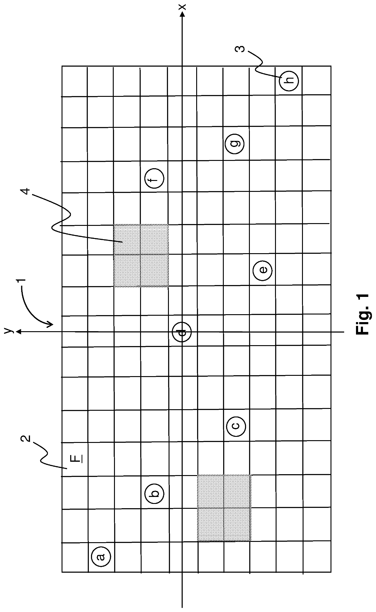
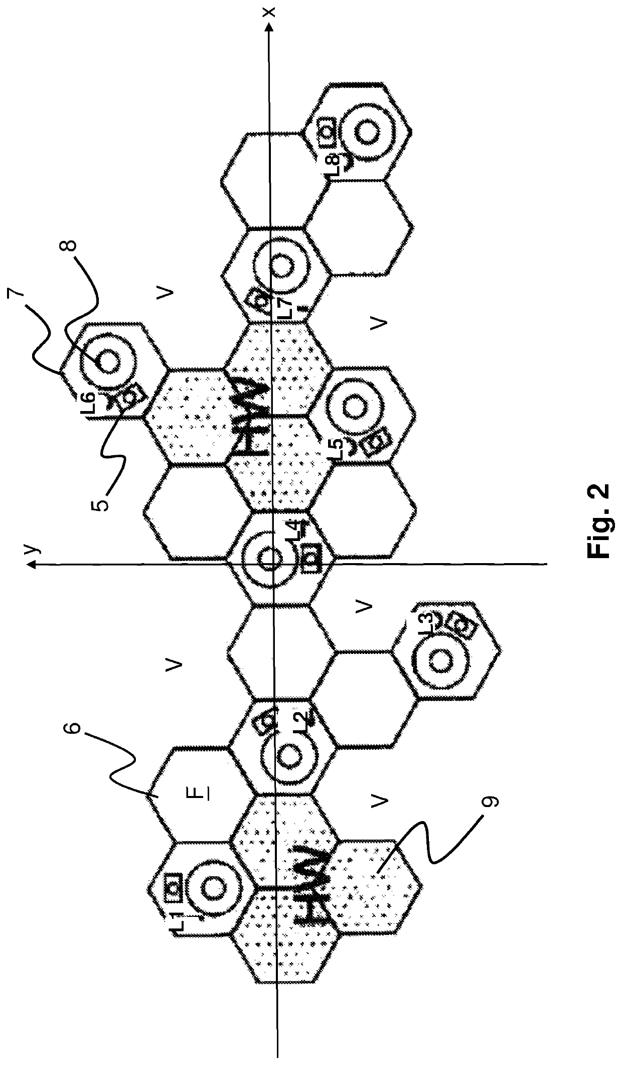
[0083]The following four examples show some of the possibilities of the sound wall according to the present invention. In all examples, the signal below fL=100 Hz is provided to all speakers, but it is understood that fL may be chosen differently, inter alia dependent on the frequency response and maximum output characteristic of the specific loudspeaker units used in the sound wall.

[0084](1) Mono: The sum of the left and right signals are fed to speaker d in FIG. 1 or L4 in FIG. 2. This setup will make the entire sound image appear at the position of speaker d or L4, respectively, no matter where the listener is situated. Therefore, speech intelligibility is high and the sound stage is stable. The level will increase closer to the speaker d or L4, respectively.

[0085](2) Stereo: The left channel is fed to loudspeaker b in FIG. 1 or to L2 in FIG. 2 and the right channel is fed to loudspeaker g in FIG. 1 or to L7 in FIG. 2. This distribution will create a sweet spot stereo image in th...


PUM


Abstract

The invention relates to a sound wall comprising in total M elements comprising a front face (F), where the sound wall (1) has a lateral extension along an x-axis and a vertical extension along a y-axis, where the sound wall (1) comprises N elements (3), where N≤M, which N elements in the front face (F) of each respective of these N elements are provided with a sound radiating unit, such as one or more loudspeaker units, configured to radiate sound energy from the respective front face and into the surroundings, such that a sound field can be created in front of the sound wall; where the sound wall is provided with signal providing means configured to provide the sound radiating units with a signal that is a combination of input signals, such as the left and right channel signals S1(t), S2(t) of a stereophonic signal. In embodiments of the invention, the sound wall (1) further comprises A elements (2), where A≤M−N, which A elements (2) are provided with sound absorbing means associated with the front face (F), whereby the sound wall (1) can be used to reduce the reverberation time of a room or other enclosure, in which the sound wall (1) is provided and / or H elements (4), where H≤M−N−A, which H elements (4) comprises hardware components configured to control and provide signals to the sound radiating units in said N elements (3). The invention also relates to a method for controlling a sound field in front of the sound wall.

Description

CROSS-REFERENCE TO RELATED APPLICATIONS[0001]The present application is a National Stage Application under 35 U.S.C. § 371 of PCT / DK2016 / 000048, filed Dec. 9, 2016, which claims priority to DK Priority Application Number PA 2015 00801, filed Dec. 11, 2015, the contents of each of which are hereby incorporated by reference in their entireties, for all purposes.TECHNICAL FIELD[0002]The present invention relates generally to loudspeaker systems and more specifically to such systems comprising a plurality of loudspeakers configured to provide a sound image, such as a monophonic sound image or a stereophonic sound image or a multichannel sound image, in a listening room.BACKGROUND OF THE INVENTION[0003]A traditional stereophonic (or other kind of multi-channel) loudspeaker system comprises at least two, and often more, separate loudspeaker boxes or cabinets provided with loudspeaker units. Although there exist many examples of compact loudspeaker boxes or cabinets that may fit into the i...

Claims


Application Information

Patent Timeline
Patent Type & Authority Patents(United States)
IPC IPC(8): G10K11/178H04R1/40H04R3/12H04R5/02H04S5/00
CPCH04R1/403H04R5/02H04S5/005H04R3/12H04R2201/401H04S5/00
Inventor DYREBY, JAKOB
Owner BANG & OLUFSEN
Why Eureka
Try Eureka