Shoulder sling with means for anchoring equipment

a shoulder sling and shoulder technology, applied in the direction of travelling carriers, travelling articles, travelling sacks, etc., can solve the problems of presenting danger to the attached cameras and accessories, the disadvantage of the free movement of the camera sliders offered by these state of the art slings and harnesses, etc., and achieve the effect of robust and durable anchoring

Active Publication Date: 2020-02-18
SWAGGART MATTHEW
View PDF36 Cites 1 Cited by
  • Summary
  • Abstract
  • Description
  • Claims
  • Application Information

AI Technical Summary

Benefits of technology

[0009]Another object of the present invention is to provide a means for limiting the movement of a camera hanging on a camera slider from a camera harness without need for complicated or awkward camera positioning. A feature of the invention is that the anchoring means can quickly and easily be attached to a hanging camera with minimal movement of the camera. An advantage of the invention is that this rapid attachment allows a user to begin active movements following a subject without wasting time awkwardly positioning a camera into a stable position. Similarly, an advantage of the invention is rapid detachment of the anchoring means from a hanging camera. A feature of the invention is that one hand movement can release the anchoring means and release the camera to a free-shooting configuration.
[0010]Yet another object of the present invention is to provide a robust and durable anchoring means for a camera suspended on a camera slider. A feature of the invention is the use of durable and tough materials in the construction of the anchoring means. An advantage of the invention is that the anchoring means strongly resists movement by an anchored camera.
[0011]Still yet another object of the present invention is to provide multiple anchoring means to a camera suspended on a camera slider. A feature of the invention is a strap that can be used either as a stabilizing strap for a camera sling by encircling the arm of a user and attaching to the sling or an anchoring means by attaching to a hanging camera. An advantage of the invention is that the user can configure the invented camera sling to be in a stable, photo-shooting configuration or quickly convert to an active movement, camera anchoring configuration.
[0012]A further advantage of the invention is that the camera does not have to be manipulated into a specific or complicated position to utilize the anchoring means. Yet another advantage of the invention is that the anchoring means can be integrally integrated into the belt of a user or in an alternative embodiment can be reversibly detachable to the belt or belt loop of a user.
[0013]Briefly, the invention provides An equipment sling with anchor point comprising: a first strap configured to overlay a shoulder of a user and extend downwardly across a front and back of said user toward a hip of the user opposite the overlaid shoulder; a secondary strap having a first end and a second end, wherein the first end is in slidable communication with the first strap along a first length of the first strap, and wherein the second end comprises means for reversibly fixing the secondary strap to said equipment; and an anchoring mechanism reversibly attached to the second end of the secondary strap such that the first end of the secondary strap is in slidable communication along a second length of the first strap, wherein the second length is shorter than the first length.
[0014]Also provided is a method for limiting movement of equipment suspended from a sling comprising: providing a shoulder sling having a primary strap configured to overlay a shoulder of a user and extend downwardly across a front and back of said user toward a hip of the user opposite the overlaid shoulder and equipment suspended from said primary strap by a secondary strap, wherein the secondary strap is in slidable communication with the primary strap; providing an anchoring mechanism that reversibly limits a range of movement of the secondary strap along the primary strap when the anchoring mechanism is reversibly attached to the secondary strap; and reversibly attaching said anchoring mechanism to said secondary strap.

Problems solved by technology

With the freedom of movement of the camera sliders offered by these state of the art slings and harnesses also came a disadvantage.
As the camera sliders allow easy movement along the length of a camera sling and harness, the cameras tend to swing and bounce during periods of high activity of a user, representing danger to the attached cameras and accessories.

Method used


Image

  • Shoulder sling with means for anchoring equipment
  • Shoulder sling with means for anchoring equipment
  • Shoulder sling with means for anchoring equipment

Examples


Embodiment Construction

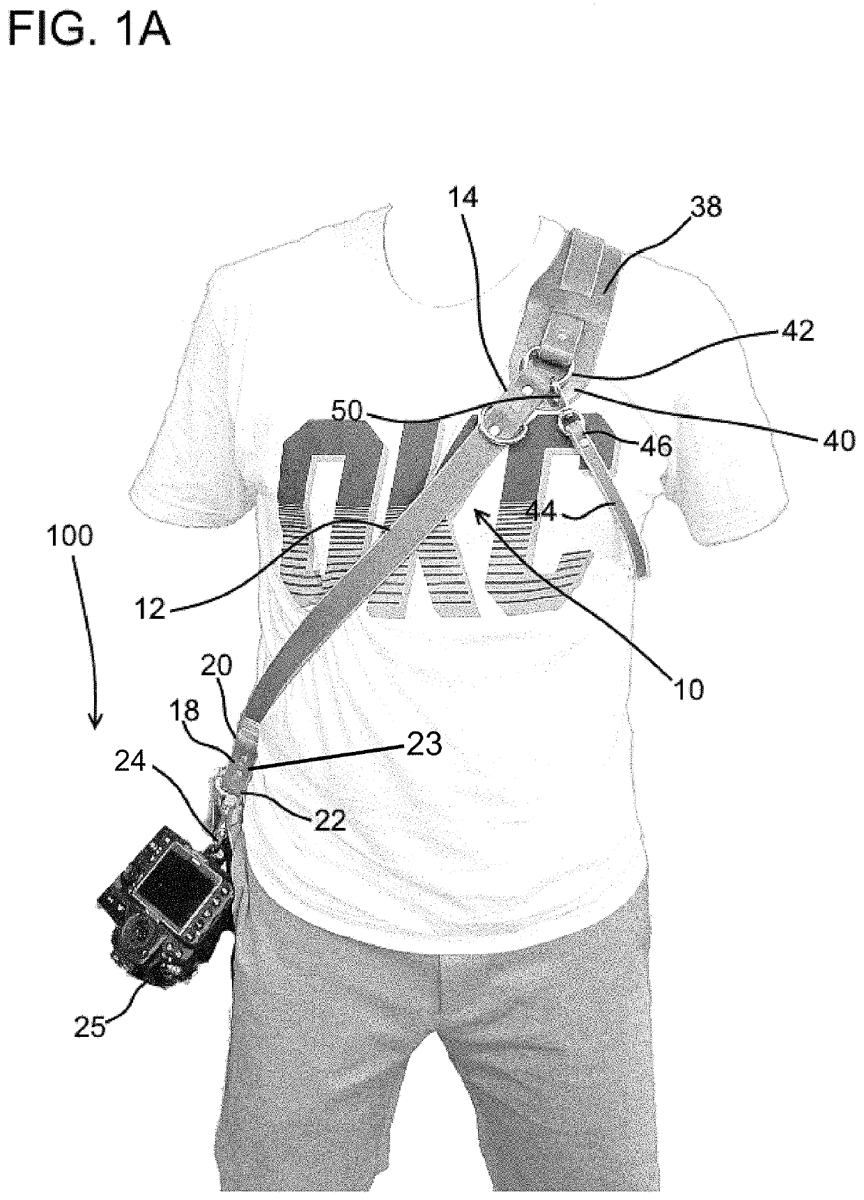
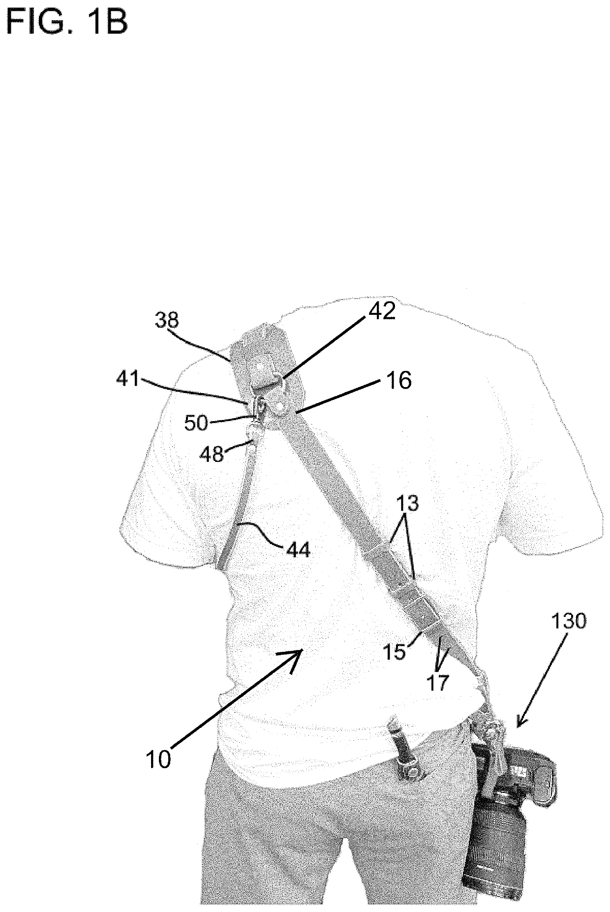
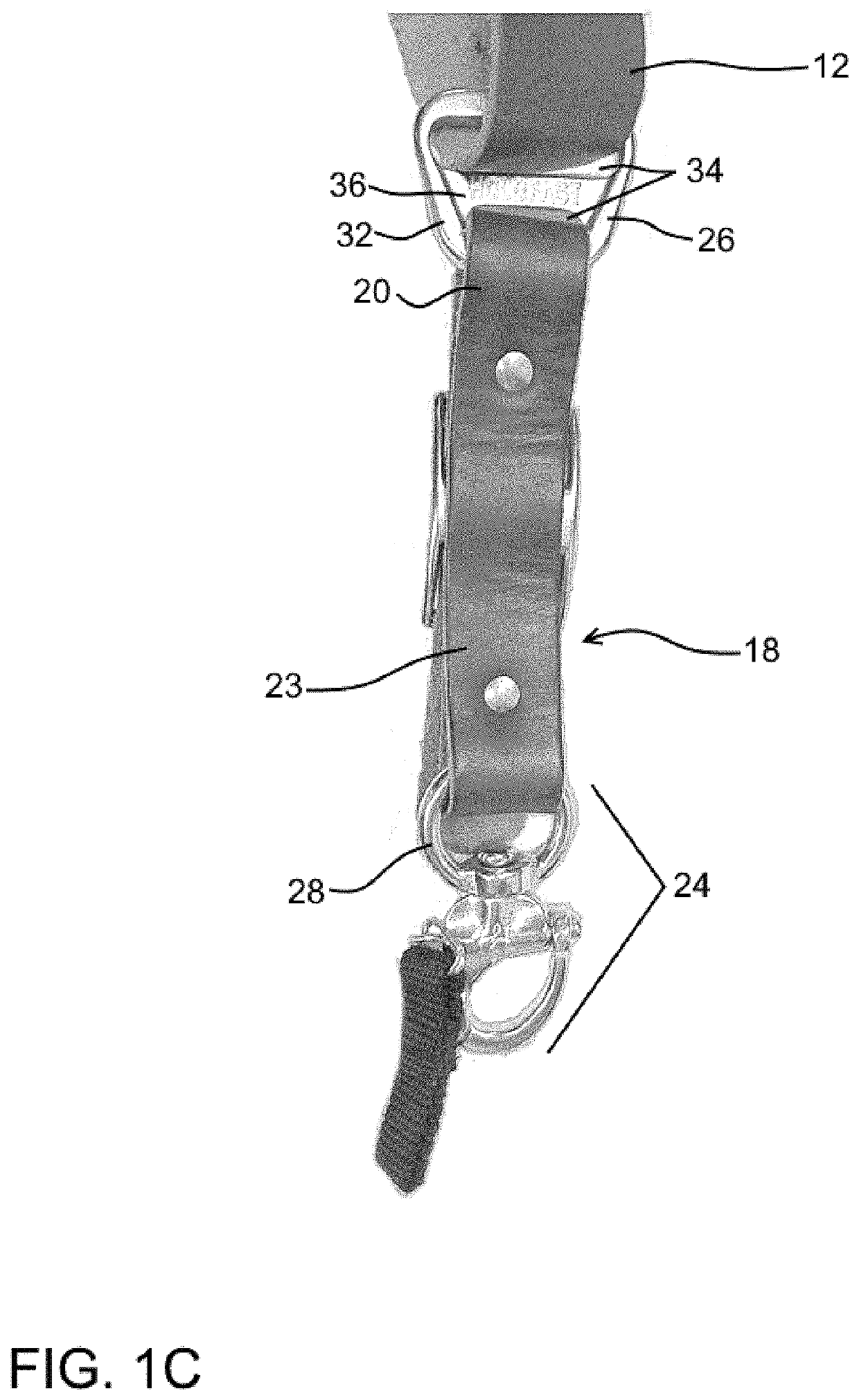
[0022]The foregoing summary, as well as the following detailed description of certain embodiments of the present invention, will be better understood when read in conjunction with the appended drawings.

[0023]As used herein, an element or step recited in the singular and preceded with the word “a” or “an” should be understood as not excluding plural said elements or steps, unless such exclusion is explicitly stated. Furthermore, references to “one embodiment” of the present invention are not intended to be interpreted as excluding the existence of additional embodiments that also incorporate the recited features. Moreover, unless explicitly stated to the contrary, embodiments “comprising” or “having” an element or a plurality of elements having a particular property may include additional such elements not having that property. As stated herein, “slidable communication” between two components means that one component may slide along the longitudinal axis of the other.

[0024]The presen...


PUM


Abstract

Briefly the invention provides a shoulder sling supporting equipment from a slider that is in slidable communication with the length of the shoulder sling, the sling also having a reversibly engagable anchoring mechanism to limit the movement of the equipment during periods of active movement by a user. Also provided is a method for using the invented equipment sling.

Description

BACKGROUND OF THE INVENTION[0001]1. Field of the Invention[0002]This invention relates to a shoulder sling for carrying equipment, and more specifically, this invention relates to a camera sling with means to reduce the swinging of a camera during periods of activity.[0003]2. Background of the Invention[0004]Many devices exist for attaching a camera to a user, with slings and harnesses being the most popular currently at the time of this application. State of the art camera slings and harnesses feature camera sliders. These sliders attach slidably to the harness or sling at one end and to a camera at the other. This configuration allows the camera to hang securely and hands-free from a harness or sling while not in use and enables a user to grab the hanging camera and slide it up to a shooting position with no lag time.[0005]The invention of these camera harnesses and slings with camera sliders improved on the convenience of previous carrying devices by providing hands-free carrying...

Claims


Application Information

Patent Timeline
Patent Type & Authority Patents(United States)
IPC IPC(8): A45F3/14A45F5/02A45F3/12
CPCA45F5/021A45F3/12A45F3/14A45F2200/0533A45F2003/142
Inventor SWAGGART, MATTHEW
Owner SWAGGART MATTHEW
Why Eureka
Try Eureka