
Suspended grille active shutter

a technology of active shutter and suspension, which is applied in the direction of vehicle sub-unit features, component optimization, propulsion cooling, etc., can solve the problems of high repair cost, large damage to actuators, and relatively expensive devices of actuators, so as to reduce the risks of bodily injury and reduce material damage

Active Publication Date: 2020-02-18
VALEO SYST THERMIQUES
View PDF20 Cites 2 Cited by
  • Summary
  • Abstract
  • Description
  • Claims
  • Application Information

AI Technical Summary

Benefits of technology

The invention is an air inlet management device that has a flexible duct which can absorb energy from impact and prevent damage to the device. The flexible duct is also designed to protect the device from vibrations and allow it to return to its initial position if necessary. The device uses materials such as polypropylene and ethylene propylene diene monomer which exhibit these properties. The technical effect of this invention is to provide protection against impact and vibrations to the air inlet management device.

Problems solved by technology

In addition, the actuator is a relatively expensive device, which is also very heavy.
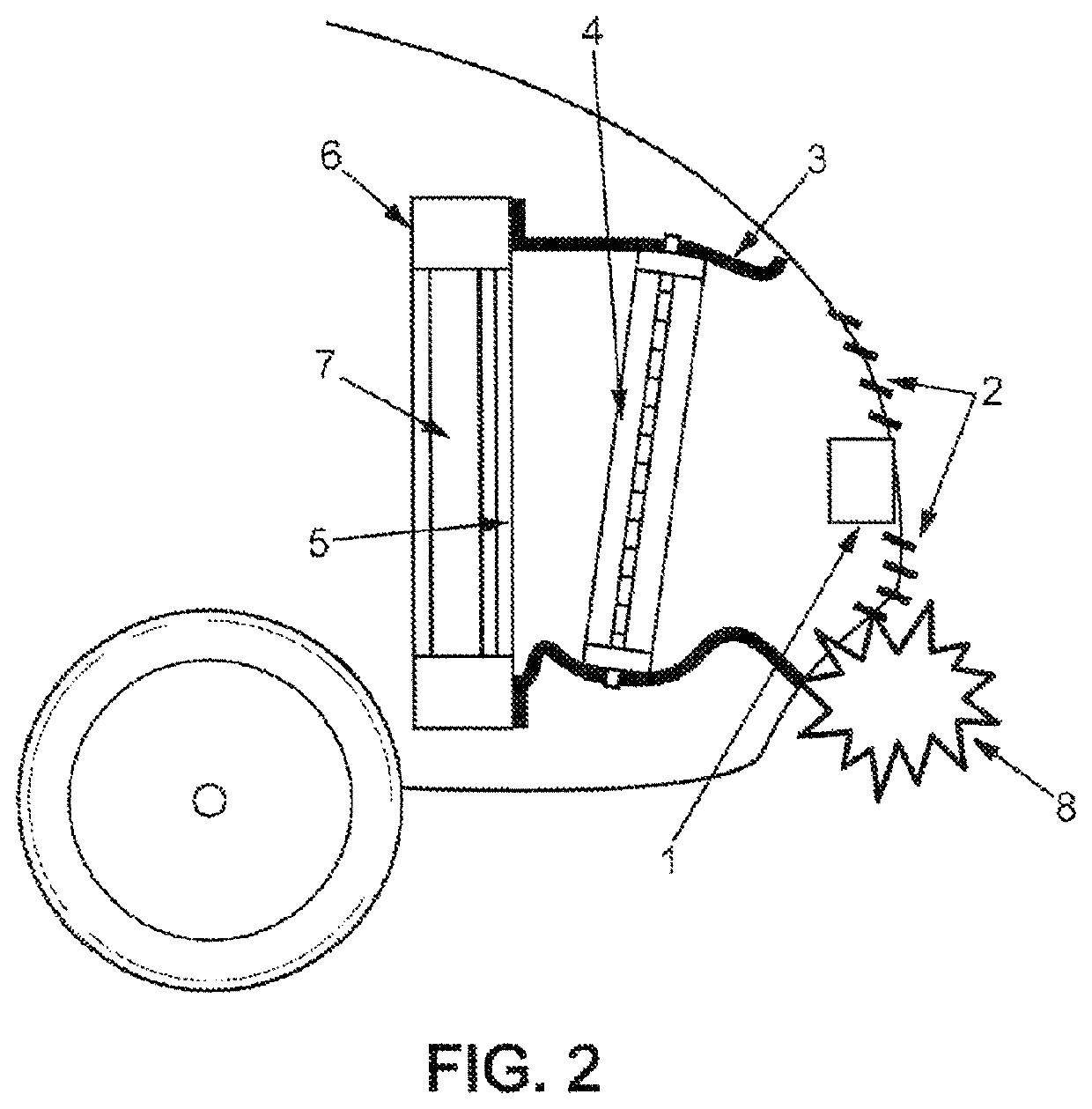
In the event of impact, the actuator is often damaged, which involves high repair costs.
Furthermore, in the event of an impact with a pedestrian, the actuator is likely to cause more serious injuries than those which may be caused solely by the flaps of the AGS.

Method used


Image

  • Suspended grille active shutter
  • Suspended grille active shutter

Examples


first embodiment

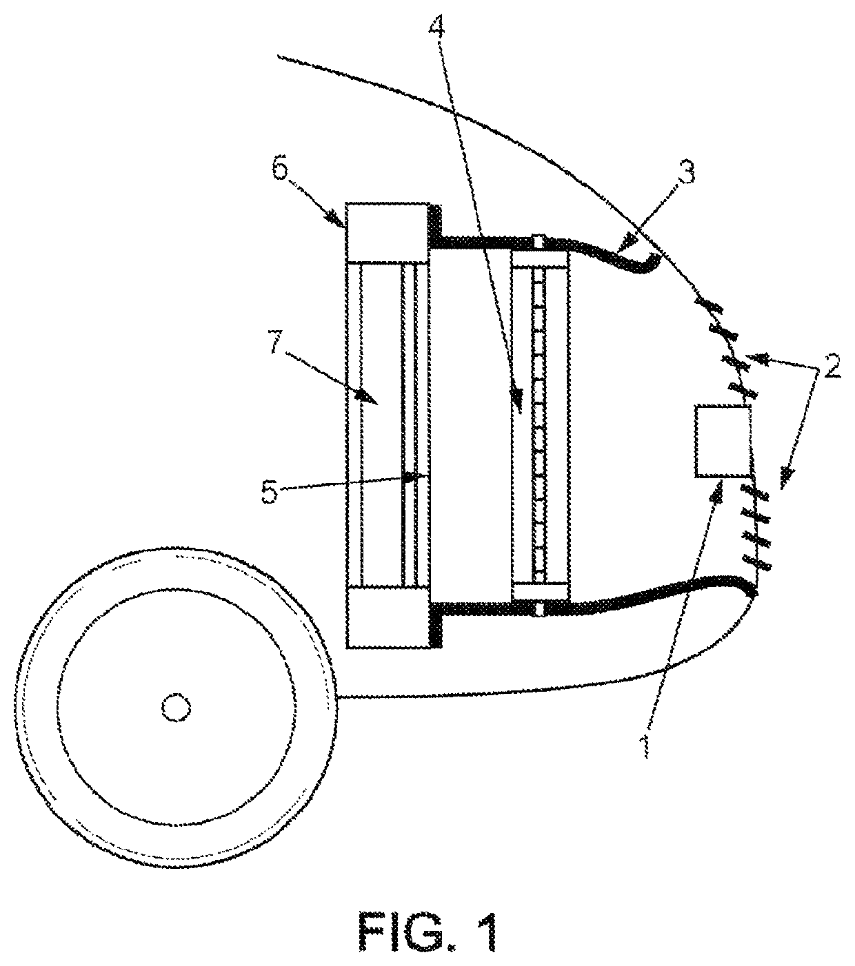
[0020]A first embodiment relates to an air inlet management device for a motor vehicle. This device comprises a flexible duct 3 for guiding the air entering via a radiator grille of a motor vehicle.

[0021]A shutter device 4 is fixed in the flexible duct 3.

[0022]Thus, when the air inlet management device is installed in a motor vehicle, and when this motor vehicle moves, the air which penetrates via the front of the vehicle (because of the relative speed of the vehicle in relation to the air) is guided by the flexible duct 3 towards the shutter device 4.

[0023]If the latter is in the closed position, the flow of air is blocked, which reduces the drag of the vehicle and accordingly the fuel consumption and CO2 emissions.

[0024]If, on the other hand, the shutter device 4 is in the open position (in order to increase the cooling of the engine), the flow of air continues on its way until it arrives at the radiator 7, being guided as it does so by the flexible duct 3. A suchlike flow of air ...

fourth embodiment

[0029] the flexible duct 3 of an air inlet management device according to one of the previous embodiments is made of thermoplastic polymer. It may, in theory, be made of natural or artificial rubber, even though this is often quite expensive.

[0030]According to a fifth embodiment, the thermoplastic polymer of an air inlet management device according to the fourth embodiment is a polypropylene, which in particular exhibits the advantage of being inexpensive, resistant to fatigue and flexing, very light and recyclable.

[0031]According to a sixth embodiment, the thermoplastic polymer of an air inlet management device according to the fourth embodiment is an ethylene propylene diene monomer (often designated by its acronym EPDM), which in particular exhibits the advantage of being resistant to oxidation, to adverse weather, to light, to cold and to acids.

seventh embodiment

[0032] the flexible duct 3 of an air inlet management device according to one of the preceding embodiment is configured to be fixed by one extremity to the radiator grille of a motor vehicle. The duct is thus capable of guiding the air from its entry into the vehicle via the radiator grille, which minimizes any air losses.


PUM


Abstract

An inlet-air management device for a motor vehicle may include a flexible duct for guiding the air entering via a motor vehicle grille and a shutter device fixed in the flexible duct. Additionally, an inlet-air management device is configured to be fixed in a motor vehicle via the flexible duct. Further, the shutter device is then being suspended in the motor vehicle via the flexible duct.

Description

BACKGROUND[0001]The object of the invention is an air inlet management device for a motor vehicle. A suchlike device may comprise a shutter device, sometimes referred to as an active shutter for a radiator grille, or also as a controlled air inlet module. A suchlike device is very often designated by the acronym AGS, which derives from the English expression “Active Grille Shutter”. The device permits the access of the air via a radiator grille of a motor vehicle to be opened or closed. In the open position, the air may circulate through the radiator grille and may participate in the cooling of the engine of the motor vehicle. In the closed position, the air does not penetrate via the radiator grille, which reduces the drag and thus permits the consumption of fuel and the emission of CO2 to be reduced. The AGS thus permits the consumption of energy and the pollution to be reduced when the engine does not require to be cooled by the outdoor air.[0002]It is helpful at the design stage...

Claims


Application Information

Patent Timeline
Patent Type & Authority Patents(United States)
IPC IPC(8): B60K11/00B60K11/08
CPCB60K11/085B60Y2306/01Y02T10/88
Inventor VACCA, FRÉDÉRIC
Owner VALEO SYST THERMIQUES
Learn More