Insulated wire, coil and electrical or electronic equipment

a technology of insulated wires and coils, applied in the direction of insulated conductors/cables, insulated conductors, cables, etc., can solve the problems of high partial discharge inception voltage, high dielectric strength, and high mechanical properties

Active Publication Date: 2020-02-18
ESSEX FURUKAWA MAGNET WIRE LLC
View PDF13 Cites 0 Cited by
  • Summary
  • Abstract
  • Description
  • Claims
  • Application Information

AI Technical Summary

Benefits of technology

[0031]According to the present invention, it is possible to provide an insulated wire, a coil and an electrical or electronic equipment having high dielectric strength (dielectric breakdown voltage) and a high partial discharge inception voltage even in case of having a thick enamel insulating layer, and having excellent mechanical characteristics such as heat resistance and notched edgewise bending.

Problems solved by technology

However, a corner portion of cross-section rectangular is extremely brittle to bending processing such as coil processing.
Due to this, there is a problem that a coated film cracks when the rectangular wire is processed by applying strong pressure.
In particular, it is known that the crack of the coated film tends to occur more easily as the curvature radius of the corner portion is smaller.
Furthermore, when the distance between conductors cannot be secured by making the thickness of the insulating coated film of the wound wire smaller, and the insulation performance cannot be secured.
Furthermore, when the insulating coated film of the wound wire is damaged, discharge occurs from the exposed conductor of the wound wire.

Method used


Image

  • Insulated wire, coil and electrical or electronic equipment
  • Insulated wire, coil and electrical or electronic equipment

Examples


example 1

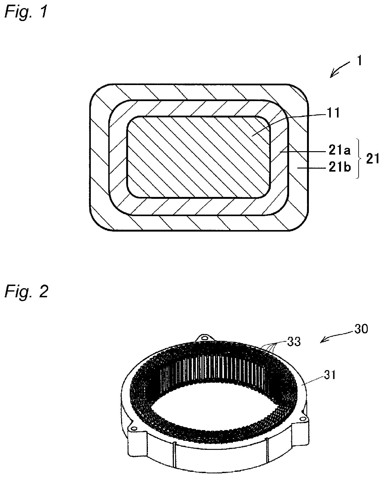
[0174]A rectangular conductor having rectangular cross-section (long side 3.2 mm×short side 1.5 mm, curvature radius of chamfered edge at four corners r=0.3 mm) (copper having an oxygen content of 15 ppm) was used.

[0175]A polyimide (PI) varnish [trade name: U-IMIDE, manufactured by Unitika Ltd., relative permittivity: 3.2] was applied on the surface of the conductor 11 using a die having a cross-sectional shape similar to that of the conductor, and the wire was passed through the interior of a natural convection type firing furnace having a furnace length of 5 m and having the temperature inside the furnace set to 300° C. to 500° C. at a speed that provided a passage time of 5 to 10 seconds. This operation was repeated several times to form an enamel insulating layer formed from a thermosetting resin having a thickness of 60 μm, and thus an enamel wire was obtained.

[0176]With the obtained enamel wire as a core wire, an extruded insulating layer composed of a thermoplastic resin was ...

examples 2 and 3

[0178]Insulated wires composed of one enamel insulating layer and one extruded insulating layer on the conductor were produced in the same manner as in Example 1, except that the resin having the relative permittivity as described in the Table 1 was used, and the thicknesses of the enamel insulating layer and the extruded insulating layer were changed as shown in the Table 1.

example 4

[0179]A polyimide (PI) varnish [trade name: U-IMIDE, manufactured by Unitika Ltd., relative permittivity: 3.2] was applied on the surface of the same conductor 11 as in Example 1 using a die having a cross-sectional shape similar to that of the conductor, and the wire was passed through the interior of a natural convection type firing furnace having a furnace length of 5 m and having the temperature inside the furnace set to 300° C. to 500° C. at a speed that provided a passage time of 5 to 10 seconds. This operation was repeated several times to form a first enamel insulating layer formed from a thermosetting resin having a thickness of 75 μm.

[0180]A PEI varnish obtained by dissolving a polyetherimide PEI [trade name: ULTEM, manufactured by SABIC, relative permittivity: 3.5] in N-methyl-2-pyrrolidone (NMP) was applied on the surface of the first enamel insulating layer using a die having a cross-sectional shape similar to that of the conductor, and the wire was passed through the i...


PUM

PropertyMeasurementUnit
thicknessaaaaaaaaaa
thicknessaaaaaaaaaa
thicknessaaaaaaaaaa

Abstract

An insulated wire, containing:a conductor having a rectangular cross-section; andan insulating coated film having at least two insulating layers laminated together on the conductor,wherein the laminated insulating coated film is composed of:an enamel insulating layer formed from a thermosetting resin on the outer periphery of the conductor, andan extruded insulating layer formed from a thermoplastic resin on the outer side of the enamel insulating layer,wherein the thickness of the enamel insulating layer is 50 μm or more, and wherein the total thickness (T) and the relative permittivity (ε) at 100° C. of the laminated insulating coated film; and the maximum thickness (Tmax), and the maximum value (εmax) and the minimum value (εmin) of the relative permittivity at 100° C. of one layer among the laminated insulating layers; satisfy all of the following relations:T≥100 μm  (1.1)Tmax≤100 μm  (1.2)1.5≤ε≤3.5  (2.1)1.0≤εmax / εmin≤1.2  (2.2)a coil; andan electrical or electronic equipment.

Description

CROSS-REFERENCE TO RELATED APPLICATIONS[0001]This application is a Continuation of PCT International Application No. PCT / JP2017 / 007713 filed on Feb. 28, 2017, which claims priority under 35 U.S.C. § 119 (a) to Japanese Patent Application No. 2016-076903 filed in Japan on Apr. 6, 2016. Each of the above applications is hereby expressly incorporated by reference, in its entirety, into the present application.TECHNICAL FIELD[0002]The present invention relates to an insulated wire, a coil, and an electrical or electronic equipment.BACKGROUND OF THE INVENTION[0003]In coils for electrical or electronic equipment including inverter-related equipment such as high-speed switching devices, inverter motors, transformers, and the like, there are used insulated electric wires (insulated wires) composed of a so-called enamel wire, insulated wires having multi-covering layers including a layer composed of an enamel resin and a covering layer composed of another kind of thermoplastic resin other th...

Claims


Application Information

Patent Timeline
Patent Type & Authority Patents(United States)
IPC IPC(8): H01B7/00H01B13/14H01B13/06H01B3/42H01B3/30H02K3/30H01F5/06H01F27/28H01B7/02
CPCH01F27/2823H01B3/307H01B3/427H01B7/0208H01B13/065H01F5/06H01B13/146H02K3/30H01B7/02H01B3/306H01B7/0275Y02T10/64
Inventor MUTO, DAISUKEOYA, MAKOTOTOMIZAWA, KEIICHIFUKUDA, HIDEOAOI, TSUNEO
Owner ESSEX FURUKAWA MAGNET WIRE LLC
Why Eureka
Try Eureka