
Automatically opening tool with sliding scale release

a technology of sliding scale and automatic opening, which is applied in the direction of metal working apparatus, etc., can solve the problems of inconvenient user service or reconfiguration, inability to service or reconfigure internally, and inability to easily service or reconfigure by users

Active Publication Date: 2020-02-25
HALUCHA WALTER +1
View PDF30 Cites 2 Cited by
  • Summary
  • Abstract
  • Description
  • Claims
  • Application Information

AI Technical Summary

Benefits of technology

An automatically opening tool with a sliding scale release according to the present disclosure can be configured for both right-hand and left-hand use. It has fewer parts and is easily serviced or reconfigured by a user. Tools in accordance with the invention can have a sliding scale that can be moved to release the tool, such as a knife. The automatically opening tool includes a U-shaped or C-shaped frame with two opposing side walls and a gap therebetween to receive the tool. Each wall can be the mirror image of the other, for reconfiguration for use by the opposite hand.
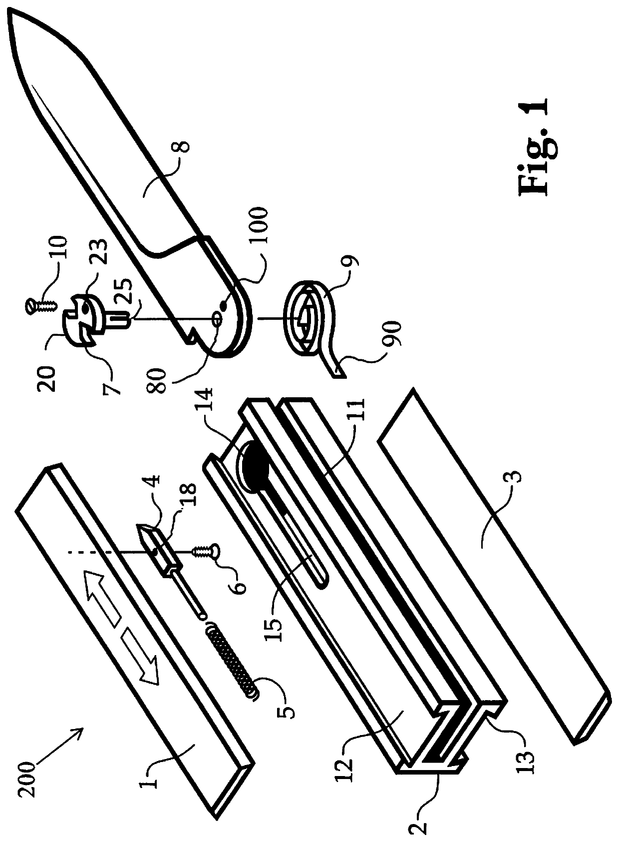
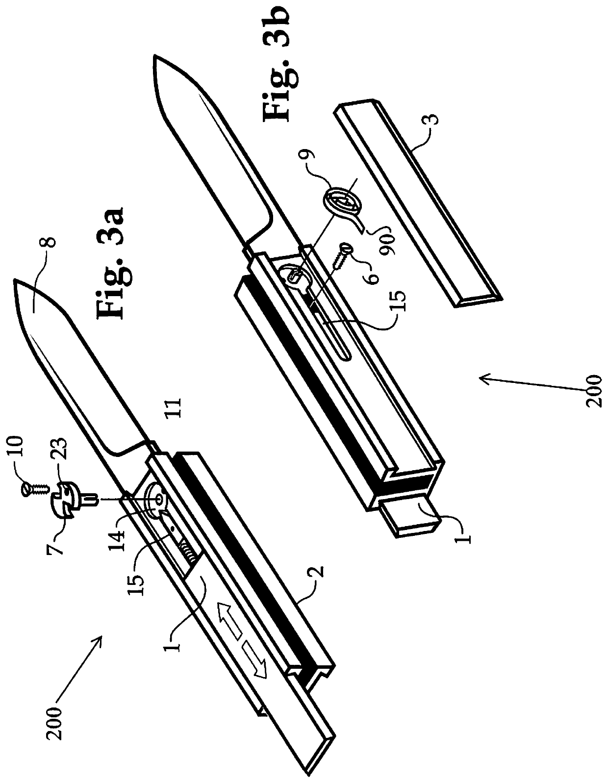
One side of the tool handle includes a sliding cover (scale) coupled to the sear. The cam is biased to bias the tool into the open position. If the tool is locked in the closed position, sliding the scale proximally can unlock the cam and permit the resilient member to rotate the cam, which in turn, kicks open the tool. Releasing the handle can permit the sear to advance into the cam and eventually the groove in the cam and lock the tool in an open position. To close the tool, the handle is again slid proximally to release the cam from the sear, and the tool can be closed by hand. The scale / cover is released and the sear is resiliently urged in the distal direction and engages a groove on the cam to lock the tool back in the closed position.
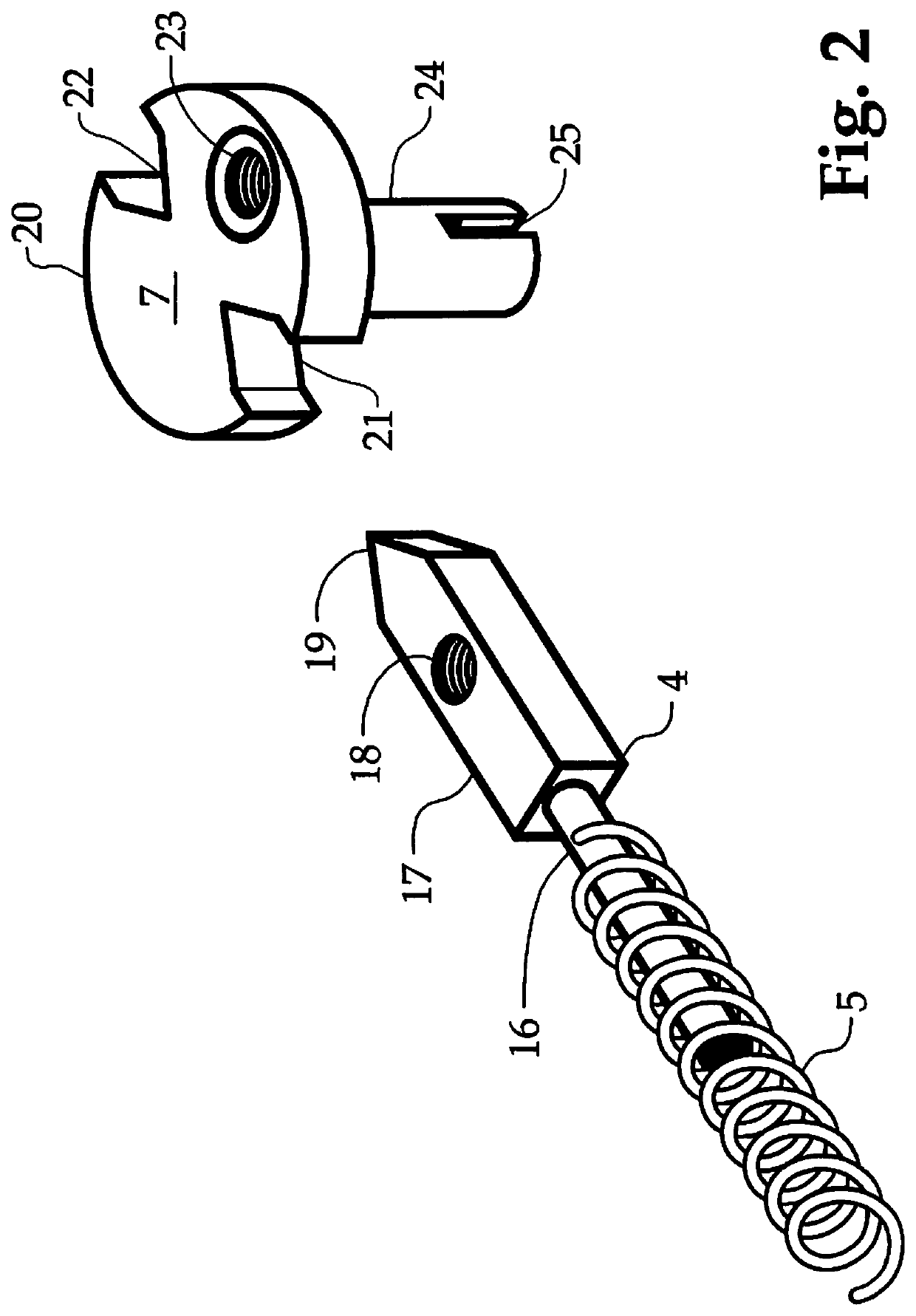
The major components of a tool in accordance with the invention comprises the blade assembly (a blade or other tool, which is coupled to a cam, which is coupled to a resilient member such as a coil kick spring; a handle assembly (a frame and two sliding covers); and the button assembly (the sear coupled to a cover and resiliently biased into and interacting with the cam) These elements are puzzle fit and hold themselves in place. The screws or pins fasten together the moving sub-assemblies. The screws or pins are internal and need not be seen when the tool is assembled. This provides a clean outward appearance, without visible pins or screws.
The handle features and following internal parts combine to produce an external appearance of a unique operating mechanism that is sleek and without visible fasteners. The blade locking device can include a chisel point (wedge shaped) sear that by nature of its physical shape as a wedge, can force the blade to come to battery or precisely stop in position with less wiggle or play. The chisel point sear can interact with a matching V-notch cam surface on a shaft, such as a step-shaft part in a fashion that normal metal fatigue or abrasive wear is not detrimental to the location fit of said parts. Subsequent use will not adversely affect blade alignment, but rather, can cause the contact surface to sharpen and improve the wedge fit.
A multifunction step shaft and coil kick spring in accordance with the invention can be manufactured with a thin profile, so as to be easily concealed under the exterior scale cover plates. Using multifunction parts can reduce the total number of parts, which can include 1 blade, 1 sear, 1 sear shaft, 2 handle covers, 1 frame, 2 springs, and 2 screws. The parts can be easily disassembled and reassembled by the user, as opposed to a factory permanent pinned assembly.
The internal parts can be configured such that the same parts can be used in any blade (or other tool) size and or external profile appearance and provide an easy interchangeability of parts.

Problems solved by technology

Typically, they are not internally user serviceable, and are not readily reconfigurable for both left-hand and right-hand activation. FIG. 5a shows a Flylock with the scale installed. FIG. 5b shows a Flylock with the scale removed.
This makes them inconvenient for users to service or reconfigure.
The resulting tolerance fit leave micro-gaps in the machinery that have a cumulative effect resulting in potential blade wiggle in either open or closed positions.
This is observable in surviving Flylock knives manufactured in the early 1900's, and also in modern scale release knives, as part surfaces wear with age, increasing the loose play in an “locked” blade.

Method used


Image

  • Automatically opening tool with sliding scale release
  • Automatically opening tool with sliding scale release
  • Automatically opening tool with sliding scale release

Examples


Embodiment Construction

The present disclosure may be understood more readily by reference to the following detailed description of the disclosure taken in connection with the accompanying drawing figures, which form a part of this disclosure. It is to be understood that this disclosure is not limited to the specific devices, methods, conditions or parameters described and / or shown herein, and that the terminology used herein is for the purpose of describing particular embodiments by way of example only and is not intended to be limiting of the claimed disclosure.

Also, as used in the specification and including the appended claims, the singular forms “a,”“an,” and “the” include the plural, and reference to a particular numerical value includes at least that particular value, unless the context clearly dictates otherwise. Ranges may be expressed herein as from “about” or “approximately” one particular value and / or to “about” or “approximately” another particular value. When such a range is expressed, anothe...


PUM


Abstract

An automatically opening tool with a sliding scale release. The assembly includes a modular body; a tool; a gear assembly attached to the tool; a first resilient member for rotating the tool; a sear configured to mate with the gear assembly; a second resilient member for imparting a resilient force to the sear; and cover plates. When the tool is closed, moving the cover plate causes the tool to open automatically.

Description

BACKGROUNDThe invention relates generally to spring-activated tools, such as knives, which can be opened automatically with the activation of a release.Automatic knives and other tools with spring loaded blades have a variety of configurations and release button designs. For example, some knives have a reciprocating (sliding) button and are referred to as having Flylock mechanisms. Existing Flylock sliding buttons generally move along the long longitudinal axis of the knife, within a cavity in the front, distal portion of the handle. As used herein, for purposes of reference only, an open knife will be referred to as oriented with its tip at its distal end and its blade edge facing upwards, to define a front left side of the handle and a rear right side of the handle. When closed, the tip will face the proximal direction with the blade edge facing downwards with a front left handle side and a right rear handle side.The side handle portion of a flylock design knife may only be a cove...

Claims


Application Information

Patent Timeline
Patent Type & Authority Patents(United States)
IPC IPC(8): B26B1/04
CPCB26B1/042B26B1/048B26B1/04
Inventor HALUCHA, WALTER
Owner HALUCHA WALTER
Learn More