Batcher gate for asphalt silo handling

a technology for asphalt silo and gate, which is applied in the field of asphalt plants, can solve the problems of affecting the quality of asphalt silo, affecting the service life of asphalt silo, etc., and achieves the effect of convenient inspection, maintenance and servi

Active Publication Date: 2022-01-18
CWMF CORP
View PDF28 Cites 0 Cited by
  • Summary
  • Abstract
  • Description
  • Claims
  • Application Information

AI Technical Summary

Benefits of technology

[0020]A first object of the invention is to provide a batcher gate that will evenly distribute materials of differing weights and densities. A second object of the invention is to provide a batcher gate that is relatively easily inspected, maintained, and serviced, without the need to remove the batcher from silo. Another object of the present invention is to enable an asphalt plant operator to intuitively inspect, maintain, and service a batcher, to thereby maintain proper operation and thereby obtain the necessary benefits provided by a batcher.

Problems solved by technology

There are several challenges to production of high quality asphalt.
One of these is referred to as segregation, which is quite simply an undesirable separation of materials.
Unfortunately, if the aggregate separates based upon mass per unit particle size, then the mix is greatly harmed.
Unfortunately, with these designs the gate opens from one side first, spilling the material in a combined horizontal spread and vertical drop.
As already noted, the challenge with the horizontal component of motion is that larger and more dense materials tend to get displaced differently than lighter and less dense components.
Unfortunately, both are prone to another problem.
Over time, the moving parts of the gates will tend to get dirty, clogged, and sticky, making the gates difficult to operate or erratic.
When failures occur, the repairs are often so difficult that the plant operators will often simply pry the batcher gates open and allow the materials to pass through the batcher unobstructed.
As may be apparent, this defeats the purpose and much needed benefits provided by the batcher.

Method used


Image

  • Batcher gate for asphalt silo handling
  • Batcher gate for asphalt silo handling
  • Batcher gate for asphalt silo handling

Examples


Embodiment Construction

[0028]Manifested in the preferred embodiment, the present invention provides a batcher gate that may more easily be maintained and serviced, enabling an asphalt plant to obtain the necessary benefits provided by the batcher with very little down or idle time required for service or repair.

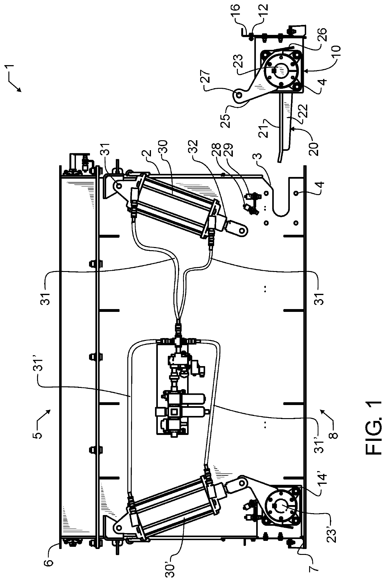
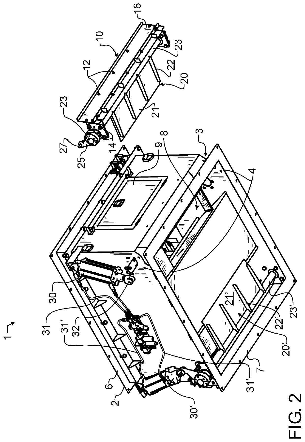
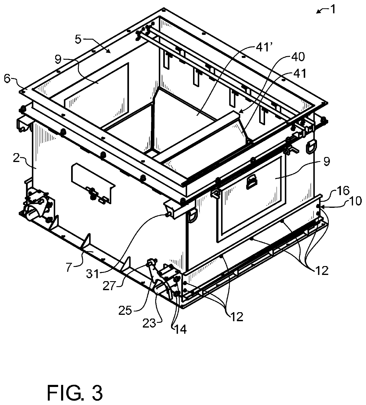
[0029]In a preferred embodiment of the invention illustrated in FIGS. 1-6, an asphalt batcher 1 is comprised of a receptacle body 2 having at least one gate assembly opening 3 visible in FIGS. 1 and 2 formed in a lower side of receptacle body 2. Adjacent to gate assembly opening 3 are a plurality of gate assembly fastener holes 4, also best visible in FIGS. 1 and 2. At the top of preferred embodiment asphalt batcher 1 there is a batcher inlet opening 5 into receptacle body 2, the opening 5 suitable for receiving asphalt components and mixtures. Batcher upper coupling flange 6 provides a flat surface with a plurality of bolt holes which facilitates coupling batcher inlet opening 5 to other common in...


PUM


Abstract

An asphalt batcher has top and bottom coupling flanges that bolt to a silo, conveyor, and related apparatus. The batcher includes a receptacle for selectively receiving and retaining materials. The receptacle has a material splitter to divide material flowing into the batcher into at least two separate funnels. Adjacent to the outlet, each of the funnels have a receptacle side wall opening. At least one pair of removable batcher gate assemblies are readily inserted into and removed from the receptacle side wall openings. Each batcher gate assembly has a batcher gate door. The pair of batcher gate doors are placed offset from center, closer to the opposed outer walls, and open toward each other and therefore the center to guide materials from the batcher receptacle body out of the batcher and into the silo center. Receptacle side wall access doors provide inspection of and access to the two funnels.

Description

CROSS REFERENCE TO RELATED APPLICATIONS[0001]The present application claims the benefit of United States provisional patent application 62 / 774,859 filed Dec. 3, 2018 of like title and inventorship, the teachings and entire contents which are incorporated herein by reference.BACKGROUND OF THE INVENTION1. Field of the Invention[0002]The present invention pertains generally to asphalt plants, and more particularly to an improved batcher gate used to introduce material into an asphalt holding silo.2. Description of the Related Art[0003]In the production of high quality asphalt mix used for the production of roadways and for other purposes, asphalt mixes may be prepared and stored in an asphalt storage silo. The storage silo is typically designed to maintain the asphalt mix at a consistent temperature until discharged.[0004]There are several challenges to production of high quality asphalt. One of these is referred to as segregation, which is quite simply an undesirable separation of mat...

Claims


Application Information

Patent Timeline
Patent Type & Authority Patents(United States)
IPC IPC(8): B65D88/58
CPCB65D88/58E01C19/1059
Inventor MICK, TRAVIS J.
Owner CWMF CORP
Why Eureka
Try Eureka