Vehicle control apparatus

a control apparatus and vehicle technology, applied in the direction of battery/cell propulsion, engine-driven generator propulsion, transportation and packaging, etc., can solve the problems of reducing shifting performance, large shock or other behavior reducing shifting performance, etc., and achieve the effect of reducing the length of tim

Active Publication Date: 2020-02-25
TOYOTA JIDOSHA KK
View PDF6 Cites 1 Cited by
  • Summary
  • Abstract
  • Description
  • Claims
  • Application Information

AI Technical Summary

Benefits of technology

Among shift-down actions to be executed in the mechanically-operated transmission mechanism, there is a shift-down action to establish one of a plurality of gear positions by engagement of a one-way clutch. This shift-down action is executed by the engagement of the one-way clutch, which is automatically made after release of a releasing engagement device that is one of a plurality of engagement devices to be released in the shift-down action. When the shift-down action in which the one-way clutch is involved is executed during decelerating run of the vehicle, if the execution of the shift-down action is initiated in a state in which an input torque inputted to the mechanically-operated transmission mechanism is lower than zero by a certain degree or more (namely, the input torque is a negative value whose absolute value is somewhat large), for example, due to a regenerative torque that is somewhat large, the one-way clutch is not engaged immediately after the releasing engagement device has been released, thereby possibly causing a behavior reducing the shifting performance, for example, giving so-called “free-running feeling” to an operator of the vehicle in absence of a decelerating torque due to failure of the immediate engagement of the one-way clutch. Where the above-described one of the gear positions can be established also by engagement of another one of the engagement devices that is disposed in parallel with the one-way clutch, it might be possible to forcibly cause the another one of the engagement devices to be placed in its engaged state, so as not to leave the situation in which the one-way clutch is not engaged in process of the shift-down action. In this case, however, the another one of the engagement devices could be engaged with a large speed difference (for example, a large speed difference between input and output elements of the another one of the engagement devices, or a large speed difference between an actual value of an input rotating speed of the mechanically-operated transmission mechanism and a value of a synchronizing rotating speed after completion of the shifting action), thereby possibly causing a large shock or other behavior reducing the shifting performance.
According to the tenth mode of the invention, the braking-torque control portion is configured, when it is determined that the input torque inputted to the mechanically-operated transmission mechanism is lower than the predetermined negative value, to switch at least a part of the regenerative torque to the wheel braking torque. Therefore, it is possible to reduce a length of time for which the execution of the shift-down action is delayed until the input torque inputted to the mechanically-operated transmission mechanism becomes not lower than the predetermined negative value.

Problems solved by technology

When the shift-down action in which the one-way clutch is involved is executed during decelerating run of the vehicle, if the execution of the shift-down action is initiated in a state in which an input torque inputted to the mechanically-operated transmission mechanism is lower than zero by a certain degree or more (namely, the input torque is a negative value whose absolute value is somewhat large), for example, due to a regenerative torque that is somewhat large, the one-way clutch is not engaged immediately after the releasing engagement device has been released, thereby possibly causing a behavior reducing the shifting performance, for example, giving so-called “free-running feeling” to an operator of the vehicle in absence of a decelerating torque due to failure of the immediate engagement of the one-way clutch.
In this case, however, the another one of the engagement devices could be engaged with a large speed difference (for example, a large speed difference between input and output elements of the another one of the engagement devices, or a large speed difference between an actual value of an input rotating speed of the mechanically-operated transmission mechanism and a value of a synchronizing rotating speed after completion of the shifting action), thereby possibly causing a large shock or other behavior reducing the shifting performance.

Method used


Image

  • Vehicle control apparatus
  • Vehicle control apparatus
  • Vehicle control apparatus

Examples


first embodiment

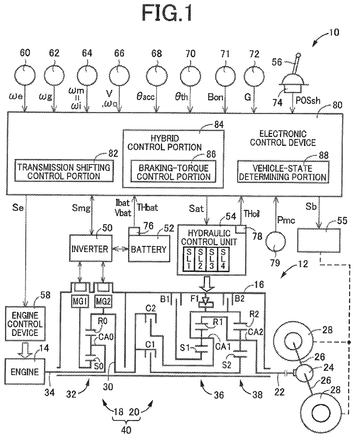
Reference is first made to FIG. 1, which is the schematic view showing an arrangement of a drive system 12 of a vehicle 10 to be controlled by a control apparatus according to the present invention, and major portions of the control apparatus to perform various controls of the vehicle 10. As shown in FIG. 1, the vehicular drive system 12 is provided with an engine 14 serving as a drive power source, an electrically-controlled continuously-variable transmission portion 18 (hereinafter referred to as “continuously-variable transmission portion 18”) connected directly or indirectly via a damper (not shown) or any other device to the engine 14, and a mechanically-operated step-variable transmission portion 20 (hereinafter referred to as “step-variable transmission portion 20) connected to an output rotary member of the continuously-variable transmission portion 18. The continuously-variable transmission portion 18 and the step-variable transmission portion 20 are disposed in series with...

second embodiment

In this second embodiment, the control apparatus according to the invention is used for controlling a vehicle 100 shown in FIG. 10, which is different from the vehicle 10 in the first embodiment in which the continuously variable transmission portion 18 and the step-variable transmission portion 20 are connected in series with each other.

As shown in FIG. 10, the vehicle 100 is a hybrid vehicle including an engine 102 serving as a drive power source, a motor / generator (rotating machine) MG also serving as the drive power source, and a power transmitting system 104. The power transmitting system 104 includes a clutch K, a torque converter 108, and an automatic transmission 110, which are disposed within a non-rotatable member in the form of a casing 106 fixed to a body of the vehicle 100, in this order of description as seen in the direction from the engine 102. The power transmitting system 104 further includes a differential gear device 112 and axles 114. The torque converter 108 ha...


PUM


Abstract

A vehicle control apparatus includes a shift control portion is configured, when determining that a shift-down action to establish one of gear positions in a transmission mechanism by release of an engagement device and engagement of a one-way clutch, is to be executed during decelerating run of the vehicle, to initiate execution of the shift-down action to establish the one of the of gear positions after an input torque inputted to the transmission mechanism becomes not lower than a predetermined negative value. The predetermined negative value is a predetermined minimum value that becomes not lower than a certain value at a point of time at which the release of the engagement device is completed in process of the shift-down action. The certain value is a value of the input torque enabling the one-way clutch to be automatically engaged.

Description

This application claims priority from Japanese Patent Application No. 2017-152044 filed on Aug. 4, 2017, the disclosure of which is herein incorporated by reference in its entirety.FIELD OF THE INVENTIONThe present invention relates to a control apparatus for a vehicle including a drive power source and a mechanically-operated transmission mechanism that is configured to transmit a drive force of the drive power source.BACKGROUND OF THE INVENTIONThere is known a control apparatus for a vehicle that includes (i) a drive power source and (ii) a mechanically-operated transmission mechanism which constitutes a part of a power transmitting path between the drive power source and drive wheels of the vehicle and which is configured to establish each of a plurality of gear positions by engagement of at least one of a plurality of engagement devices including a one-way clutch. A vehicle control apparatus disclosed in JP-2011-199959A is an example of this type of control apparatus. This docum...

Claims


Application Information

Patent Timeline
Patent Type & Authority Patents(United States)
IPC IPC(8): F16H59/18B60L7/26B60L7/18B60L50/61B60L50/16B60K6/445B60K6/547B60W20/30B60W10/18B60W30/18B60W10/11B60L7/20
CPCB60L50/61B60K6/547B60L7/26B60W20/30B60L50/16B60L7/18B60K6/445B60L2240/12B60L2240/80B60L2250/26B60W30/18127B60L2260/24B60W10/18B60L7/20B60L2240/486B60L2240/16B60L2260/30B60L2240/507B60W10/11B60W20/14B60W10/06B60W10/08B60W20/40B60W2520/10B60W2710/083B60W2710/1005B60W2710/0666B60K2006/381B60K6/38B60K6/365B60W10/115B60W20/15B60W30/18136F16H63/502B60W2510/0657B60W2510/083B60W2540/10B60W2520/105F16H2059/186Y02T10/62Y02T10/7072Y02T10/70
Inventor BABA, MASAYUKIKOBAYASHI, NOBUFUSAYOSHIKAWA, MASATOKUMAZAKI, KENTAGOTO, JUN
Owner TOYOTA JIDOSHA KK
Why Eureka
Try Eureka